Yeah I'll try the third order electrical for the tweeter. My xo point for that is actually 3kHz btw.
I am using the pair measurement for the woofers. You cant see that null because I basically buried it. That's actually what C3 is doing, thats my bad. Also thats what L2 is doing. Getting rid of that high frequency mountain.
That is good to know about large values because I was trying not to do that, but that is true how I might actually need it if it necessary.
I did work from the woofer, to mid, to tweeter btw. Yeah I didnt explain that well with my screenshots haha.
Good to know about the 3ohm minimums.
I'm working on it again right now and will post when I have something.
Last edited:
The tweeter target may be 3kHz but the actual crossing in your last pic looks closer to 2.5kHz. I think either is ok if the results look good.
With the woofers, just start with the basics. You may find that if the roll-off is steep enough, all the peaks and valleys will be low enough in SPL not to worry about them. Right now you've got too much woofer contribution in the midrange, about 600Hz to 2000Hz *. Try to bring that down some more without creating a suckout at about 500Hz if you can.
Phase match between the mids and tweeter is good up to about 1200Hz but then starts to diverge. But the mid is still contributing a fair bit between say 4kHz and 9kHz (less than about 20dB down) which probably means the off-axis response is going to do something different than the on-axis response, so I would try to reduce that too if you can. Move it to LR4 on the top end in other words.
*Analysis is based on your last pic attachment.
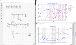
Alright here is my V.2!
So I have included the screenshots in a more cohesive way. But as you can tell from looking at them, I went back to the woofer a couple times and changed things. The process of course isnt always linear haha.
So, lets get into it.
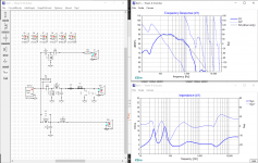
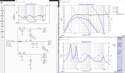
The woofer like you said could be done with less components which is A+ thinking. L1 and C2 are doing most of the work. L1 shouldering it well and then C2 shaping it to get the valley at 500Hz a little less extreme, that has been the main problem with the woofer. But doing that made the hump at ~200Hz larger, so L2 is there and brings it down just a hair.
The second screenshot is not really necessary, but it was more so to show the fit of the curve. But, the null at 3kHz was bothering me with that circuit configuration. So, I tried the first circuit config again and liked it better.
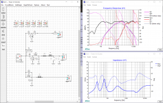
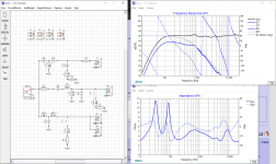
So the third screenshot is the tweeter with the LR4 at 3kHz and the mid together. While doing that I realized since the tweeter is now third order electrical, flipping the tweeter was necessary (there was a null that was created without flipping it).
The whole circuit actually still worked okay with all drivers the same polarity (none flipped). But it looked much better with the mid and tweeter flipped.
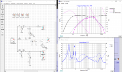
After I look screenshot 3, I went back to the woofer to fix that valley at 500Hz.
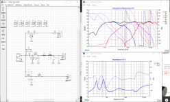
So now looking at the final screenshot.
- Tweeter and woofer phase line up perfectly, yet the mid is kinda far away.Dont know if that is something to worry about. Correction: the phase of all actually looks good.
- The impedance dips a little into 3ohms, but nothing crazy and the phase is looking good.
- All peaks are within 1dB from the fundamental. I focused on controlling peaks before the valleys.
- The valleys are within 2dB from the fundamental. Except ~4.8kHz is 3dB and so is ~13kHz.
Let me know what you think!
This is looking pretty good to me tbh.
Also, I do have some xo components on hand btw. Some left overs from my speaker building class. We were supposed to build a pair but covid happened and building one was then only required.
Here is what I have:
Inductors
- 5.4mH
- 2.5mH
- 0.51mH
- 0.62mH
Capacitors
- 2.2uF @ 250V (2)
- 2.0uF @ 250V
- 0.33uF @ 250V
- 39uF @ 400V
- 25uF @ 250V
- 0.22uF @ 250V
My inventory of these can be doubled as well. I can just take it from the speaker that was actually built from the class.
So I have included the screenshots in a more cohesive way. But as you can tell from looking at them, I went back to the woofer a couple times and changed things. The process of course isnt always linear haha.
So, lets get into it.
The woofer like you said could be done with less components which is A+ thinking. L1 and C2 are doing most of the work. L1 shouldering it well and then C2 shaping it to get the valley at 500Hz a little less extreme, that has been the main problem with the woofer. But doing that made the hump at ~200Hz larger, so L2 is there and brings it down just a hair.
The second screenshot is not really necessary, but it was more so to show the fit of the curve. But, the null at 3kHz was bothering me with that circuit configuration. So, I tried the first circuit config again and liked it better.
So the third screenshot is the tweeter with the LR4 at 3kHz and the mid together. While doing that I realized since the tweeter is now third order electrical, flipping the tweeter was necessary (there was a null that was created without flipping it).
The whole circuit actually still worked okay with all drivers the same polarity (none flipped). But it looked much better with the mid and tweeter flipped.
After I look screenshot 3, I went back to the woofer to fix that valley at 500Hz.
So now looking at the final screenshot.
- Tweeter and woofer phase line up perfectly, yet the mid is kinda far away.Dont know if that is something to worry about. Correction: the phase of all actually looks good.
- The impedance dips a little into 3ohms, but nothing crazy and the phase is looking good.
- All peaks are within 1dB from the fundamental. I focused on controlling peaks before the valleys.
- The valleys are within 2dB from the fundamental. Except ~4.8kHz is 3dB and so is ~13kHz.
Let me know what you think!
This is looking pretty good to me tbh.
Also, I do have some xo components on hand btw. Some left overs from my speaker building class. We were supposed to build a pair but covid happened and building one was then only required.
Here is what I have:
Inductors
- 5.4mH
- 2.5mH
- 0.51mH
- 0.62mH
Capacitors
- 2.2uF @ 250V (2)
- 2.0uF @ 250V
- 0.33uF @ 250V
- 39uF @ 400V
- 25uF @ 250V
- 0.22uF @ 250V
My inventory of these can be doubled as well. I can just take it from the speaker that was actually built from the class.
Attachments

Last edited:
I also want to ask this cuz I am just kinda messing around with the CC xo after I post about the towers. Doesnt hurt to see what works and what doesnt.
But, my question is about the woofers. From all the testing I took, it was always one woofer at a time. But now thinking about it, idk how that will translate to the xo. Should I have one circuit to control both woofers, or will I need two identical circuits to control each woofer.
In Xsim, should I have four drivers out front (tweeter, mid pair, right/left woofer)?
Right now I just have one woofer in Xsim. But I'm just curious on how to set that up so I can mess around with it correctly haha.
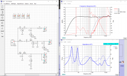
That is looking better. The FR is acceptably flat with the impedance no problem at all. Contributions from each driver look good too with xo points and slopes in acceptable ranges. Problem contributors, mostly just the tweeter Fs, are all acceptably down in SPL.
But 2 things I think could still be better and possibly a 3rd although that one is a bit of a trade-off.
Circled in the pic below, from left to right.
I'm a little bothered by that suckout at 500Hz for a higher quality speaker but it's a trade-off. You could increase the woofer roll-off by increasing C2 and then increase the mid output down low by also increasing C4 but the larger cap values are going to be a little bit more expensive and you are going to get an increase in output down around 200Hz which will need to be treated with a notch filter, again requiring some fairly large values. So 6 of one, half a dozen of another. For drivers of this quality btw, very good but not quite outstanding, all these higher value caps can be sourced from lower quality, less expensive components. The larger inductors are going to need to be iron cored for lower resistance and again much less size and expense.
I'm not sure but I don't think that you quite fully understand phase alignment yet. You understand the alignment part but not where they need to be aligned which is in the region where both drivers are contributing to the summed response.
So for eg you are correct that the tweeter and woofer are super well aligned from about 500Hz to 1300Hz but the tweeter is making absolutely no contribution to the speaker output in those frequencies. Irrelevant in other words. So it's really plus and minus an octave or so on each side of the xo (depending on slope roll-off) that matters for the 2 drivers involved.
So around both xo points, both the woofer and mid and then both the mid and tweeter don't really show great alignment. Close but it could be better. I'm going to guess that if you reverse the polarity on the mid, neither one of the reverse nulls are going to be very deep.
And then lastly you've got that sort of broad peak centered at about 8kHz on the tweeter which is a little too close to the sibilance zone for comfort. This may not be too bad for the L&R but not so good for the CC which handles all the dialogue. And if you want to closely match the L&R with the CC, then a notch filter up in that zone may be required on the L&R too. I say 'may be' because it depends on how much of a priority you place on matching those 3 speakers perfectly across the whole frequency range. I suspect it might be ok to just attach that problem in the CC and leave the L&R as is. I think what I would probably do is leave the notch out on the L&R to start with, listen to the results and then make a decision from there.
This is a subtle point that I let slide with the 2-way rears that had a higher single xo point, but with a 3-way I'm going to suggest that you include the port output because what happens to F3 on the woofer may be important to look at and you can't see that without the full box response. So either include the measured port response in the correct manner or go back to the response blender and include the box response there.
Because for the way I did my blending, I found that only 15W was necessary from the amp to get my woofer level up the the 90dB target at about 200Hz. And the importance of getting that level right relates to the F3 of the speaker. If you are setting your woofer level a couple of dB higher for eg, that means that original F3 is going to be that couple of dB lower and so the actual F3 is going to move higher in frequency although the box tuning hasn't changed at all. I find this a bit hard to explain actually so if you need to ask about it, feel free.
In terms of xo's for pairs of drivers, you definitely do not want to be putting a separate xo on each driver. Just one xo for the pair. Now in XSim, you could do the xo with separate driver responses but still you would only do 1 xo for each pair (or whatever multiples as the case may be). I guess the problem sort of comes when you put both drivers into 1 chamber as you did in the towers for the woofers and the mids and for the mids in the CC -> you can't measure the correct impedance nor the correct NF response for a single driver when you pair them up in a single chamber. So measure them together, both the FR and the impedance and then just import the files to 1 driver in XSim understanding that it represents the responses of both of them.
Now there is a way to go about it if you want but it isn't really necessary. You'd take the FF measurement separately for each paired driver, blend in the NF response (taken with both drivers wired together) for each driver and then you'd have to manipulate the impedance measured with both drivers together so that you changed from 4ohm back to 8ohm, which can be done in REW. Then XSim would sum the two 8ohm impedances back to 4ohm which is a little redundant actually and then it would also sum up the 2 separate driver responses to give you more or less what you measured when you measured the 2 together. Also a little redundant.
Attachments

Right so for the CC where the woofers are in separate chambers, in XSim you will need to wire up 2 drivers in parallel instead of just the 1 driver for the towers. Each driver is going to have the exact same response though. But you did measure the impedance and the NF response for just a single driver so that's the way that you are going to have to enter them into XSim.
Hope that helps. Btw, if you are starting to mess with the CC sim, I'll just mention that it might make things easier if you change the smoothing on the mids to something like 1/12 or even 1/6. Get rid of more of that undulation in other words.
Hope that helps. Btw, if you are starting to mess with the CC sim, I'll just mention that it might make things easier if you change the smoothing on the mids to something like 1/12 or even 1/6. Get rid of more of that undulation in other words.
You are right, I have not fully grasped the concept of phase alignment yet.
So, I want the phase to line up near the xo regions is what youre saying? Knowing this is if the phase is parallel with each other, if they are vertical together, or if they create a deep and wide null when one is revered polarity.
Also, I cannot find it right now but I remember reading that iron core inductors should be avoided if possible. I have honestly thought those were irrelevant now-a-days. What is the benefits of iron core vs the air core ones?
Yeah I should include the port response, I've been thinking the same. But how do you do that with response blender? I only saw the baffle step model and a box model. I didnt see anything for the port.
Also, I have the paired speaker measurements. You should have all my measurements Im pretty sure, if you dont lemme know!
But I also have impedance and FR measurements for both the left and right woofer in the CC. So, I can pair those up in the Xsim.
Lastly, that wide peak around 8kHz could be fixed in CC, but I think for the towers it would be okay. That hump is only like 1dB max, if that. I can also just increase the resistor one step to get it slightly lower.
So, all-in all, I need to focus on trying to fix:
- The valley around 500Hz, which might be fine with the port included.
- The phase alignment of all
- Possibly the wide peak at 8kHz, but thats optional
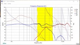
Yes, plus or minus about an octave on either side of the driver, both drivers are contributing to what you hear, depending of course on the acoustic roll-off chosen. Above and below that, you are basically only hearing a single driver. So to get the most consistent combined response from both drivers in the xo region both on-axis and off-axis, we try to align the 2 phase responses as closely as we can meaning of course that when both drivers are playing, they are both getting to your ears at about the same time. Both pics below show the 2 octaves of driver overlap (more or less) in yellow and both show very good phase alignment in that region. In 1 case, paralleling very closely and in the other, excellent vertical alignment right at the xo frequency. I think you get the concept but technically, 2 lines can be parallel and yet very far apart. So parallel and as close together as possible.
Where phase goes vertical is just an artifact of how it is being graphed btw. When the phase angle increases or decreases beyond 180 degrees, the graph simply goes back to the top or bottom and starts again. If you haven't figured it out yet, both pics below are of the exact same xo and phase alignment - I've just reversed the polarity of both drivers in 1 of them to show you how the same phase alignment can be displayed differently.
You may also want to know that there are some who take the position that phase alignment is over rated. I'm not really knowledgeable enough to know if that's true or false but I side with the good alignment camp. One other thing to note is that in a 3-way, of the 2 xo points it's possibly less important if the lower mid to woofer phase alignment isn't quite as good as the higher one. I think it's size of the wavelengths playing a role there again.
Iron core inductors may not be quite as good as air core but they are still widely used for larger values due mostly to cost and size. Generally speaking, it's a bad idea to add series resistance to your woofer circuit so you are in a bit of a pickle when you need a large inductor value there because in air cored inductors, you start to need thicker and thicker copper wire and more of it as the values get larger and larger in order to keep resistance low. And copper isn't cheap these days. Go have a look at Parts Express's inductor pages and start looking a the resistance values, cost and size of different inductors both air core and iron core. That should be enlightening.
Without a doubt, if you have the space and the budget and maybe are dealing with the highest echelon of driver quality, always go with air core. But in the real world where any or all of those aren't the case, it's perfectly acceptable to use the iron cored inductors. A sort of rule of thumb I use is to try not to pay more for the xo parts than I did for the driver. Doesn't make sense to me to throw a $40 inductor in front of a $25 driver but if the driver is worth $250, well then.......
In Response Blender, by splicing in the box response to your NF measurement you are effectively adding in the response of the port.
Maybe try a notch filter on that 8Khz hump anyways, you should see that the size of the parts are going to be so small that the additional expense and space used is going to be minimal. The filter is most likely also going to change the rest of the tweeter response just enough that some other changes may be needed to the rest of the tweeter xo, perhaps also improving the phase alignment. Maybe. But at least then you'll actually have 2 things to choose between as well as knowing what to do if you want to try it on the CC. In my sims so far, the smoothest and flattest response I got up in the HF's was with the filter in place. I also generally try out both a series notch and a parallel one because you'd think that they should but they don't always produce the exact same results. Each type will also have a different effect on the impedance which can sometimes be a deal breaker although I didn't find it important in this case. A little tip with notch filters is to more or less leave out the resistor as you get your inductor and capacitor values figured out. That way, the notch is as deep as possible and super easy to see both it's center frequency and it's Q, or how wide or narrow it is in other words. Then once you have it sized and placed right, then include the resistor and fine tune as necessary.
Attachments

Thank you, that helps a lot with phase alignment now. I do agree that phase alignment is important, especially for off-axis responses. I dont have much experience with bad phasing issues, but in school it was something we always had to take into account with anything. AC circuits and reactance stuff, very important. But even to that event, phase was always my weakest subject. Maybe cuz it was always included, but not too much talked about.
So I totally get your point where throwing a $40 inductor in front of a $25 driver is worthless. But if you get lower quality xo components in front of a lower quality driver, then, to me, thats two low quality things going on. But if you buy good xo components in front of a low quality driver, at least one thing is good. So, overall "more good" haha I'm just spitting nothing factual here.
Anyways, Im not going to be getting the best inductor or capacitors I can find, but I'm for sure not going to cheap out on them either tbh. With all the work put into the box, I dont think I can settle for going cheap in the xo.
The driver imperfections are honestly just a failure for accurate spec sheets. The spec sheets and everything made them look extremely promising. Since they were also the reference series and a very reasonable cost for the amount that had to be bought. They were the perfect choice, so I thought. Overall, still good drivers, I just feel cheated by Dayton Audio.
So, Ill include the port and work on phase issues. Also, Ill tinker with a notch filter.
And yeah, I have figured that trick out. I realized that the inductor and cap are setting the frequency in which the notch filter is, then the resistor is basically controlling how much of that frequency is being dumbed to ground.
They control the Q as well as the center frequency. There's a whole slew of cap and inductor values for any notch filter that will keep it centered on the same frequency but the widths will be different. Note also how the cap and inductor manage opposite sides of the notch depending if they're in series or parallel.
So this is the best I could do for today, but tbh probably the best I can do right now in general.
I included the port summation to the woofers blended response.
The FR is looking quite flat, definitely flat enough for my brother who does not have a tuned ear. The only thing I dont like about the FR is the valley ~4.8kHZ.
The one big thing that I was messing around with tho was phase. I could not get them to line up so nicely without the FR being just awful. I tried messing with every component and pairs of components, and just everything like 5 times, I just couldnt get it.
When I would line up the phases well, I would get really big peaks at the xo points. Or something else would go bad.
What have you come up with? Because phase is not working out for me. 😱
Also, I have just realized that my impedance is not dipping into 3ohms like twice. It kinda rides 3ohms for awhile.
Attachments
That's actually a really good FR especially for the your 1st 3-way (with 1 caveat). Riding 3ohm in the impedance will be fine for typical HT receivers. It will help though if the amp has headroom but that's almost always the case. Phase though still leaves a little to be desired. I could probably live with what you achieved at the lower xo point but I typically try to get something better at the upper one. And believe me I understand any frustration with unsuccessful attempts at trying to shape the responses the way you want and coming up short - sometimes you just want to pull your hair out. 😱😱 And just so you know, I found working with this tweeter a little challenging now and then too. The other drivers I found to be pretty straight forward.
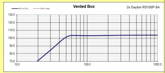
The caveat involves taking a good look at your F3 response. Your summed response is up around 90dB and I'm going to guess that your F3 is only down to about 80Hz or maybe 75Hz instead of down around 50Hz the way it was modeled. Not much point really in going vented if that port isn't contributing much. I've attached both Unibox and your response for you to take a look at the difference.
This may have a little to do with how you spliced and blended the woofer response but mostly it has to do with the interaction between the strength of the filter required on the woofer and the impedance peaks of the vented response. There are some different choices that can be made to handle this but I think the best is to just to bring the humped response down at around 170Hz with a notch filter.
This isn't uncommon in a 3-way but the problem is kind of exacerbated by the selection of smallish woofers for a 3-way. I mean I still call most drivers 150mm or under midranges, not woofers. But that's what your brother wanted, a slim design so it is what it is. The only other thing I might have tried in the design process was to look at side mounting a pair of larger woofers but that might not have worked either or that may be better left for another project. Just for next time, I have to strongly suggest that before you even purchase any drivers, you must run them through a full xo simulation with the driver spec sheet responses like you are doing right now with your measured responses. It's not always going to give you perfectly comparable results but it will usually let you know the general lay of the land and how well or not the selected rivers are going to work together. What's going to be needed in the xo gets pretty obvious as well albeit the values will probably need to be adjusted somewhat.
I haven't had the chance yet to double check what you came up with with the files I created but I've attached the xo that I came up with and am happiest with. Second order on the woofer with a notch filter on the 1st impedance peak. Second order on both filters on the mid plus both a series resistor and a parallel one before the driver. Third order on the tweeter plus a notch filter aimed up around 8kHz and an L-pad just before the driver although I suspect I've used some rather non traditional values. I liked the parallel notch placed in series better than the other way around. Phase matching is excellent between the mid and tweeter but only average between the mid and woofer. That's the best I could do though. Xo points are at 475Hz and 2300Hz. F3 is down at ~ 56Hz.
The negatives -> impedance dips just below 3ohm at about 125Hz which I think is still acceptable though. And I've got a rising response in the tweeter above about 14000Hz but mostly it's just the young kids that can hear that high so again, acceptable. Some of my shunt values on the filters are larger (or smaller as the case may be) than I would like but they aren't creating any low impedance problems that I can't live with, 2.75ohm at 125Hz being the worst of it. The tweeter notch values are tiny so easy to live with. The woofer notch values are huge and may look daunting but using an iron cored inductor and a much much cheaper non-polarized electrolytic capacitor or similar are standard choices for this kind of filter and perfectly acceptable with these drivers in my opinion.
Hope that helps. 🙂
Attachments
Here's a deeper dive into minimum impedance.
Basically every amp has an upper current limit based on the following: P = RI^2, so I = SQRT(P/R), where P is power in watts, R is resistance in ohms and I is current in amps.
So if you have a 100W amp into a 4ohm load, maximum current is going to be I=SQRT (100/4) = 5 amps. If in reality the amp can take a 3ohm load, then max current is going to be 5.77 amps.
Now look at the maximum power the woofers can take. The spec sheet says 40W max but if you look at xmax for the vented alignment in Unibox, you can't feed it more than about 20W before xmax is exceeded with 2 drivers in parallel. SPL with that btw is about 107dB at 1m before baffle step loss.
Now we need to know how much current the speaker is going to consume if you feed it those 20W. Luckily, XSim has such a chart. First add a resistor in series before the whole xo and set the value at almost nothing, so .1ohm. This will be the tool through which you can see the current draw for the whole speaker.
Now go to AddGraph -> more -> Component Current (A). Change the vertical scale to 1A so you can see what is going on a little clearer and now increase the power to 20W. And that's how much current the speaker will be drawing when it's fed 20W. At 121Hz, current draw is about 4.5 amps. So no problem for a 100W amp into a 4ohm nominal load. First pic below.
The 2nd pic is with 30W and now current consumption at 121Hz is up to 5.6 amps, which now is getting a little tight for a 100W amp (max of 5.77 amps). So if you want to get crazy and really push these drivers beyond their xmax limit but still within their power limits, a bigger amp might be in order. A 125W amp will allow you a max of 6.45 amps of current at 3ohm, so back to being within acceptable limits.
The low impedance btw is due to the large value required on the woofer shunt cap, C1, and this is primarily the reason I try to have the 1st series filter component do most of the work -> relying on the component to ground to carry too much of the load breeds lower impedance which means inefficiency and wasted power from the amp. But sometimes breaking that rule of thumb is unavoidable and then the solution I guess is making sure your amp has enough current to comfortably supply the speaker for the amount of power you want to feed them.
And lastly, note that the highest current draw is only going to happen at one specific range of frequencies, centered at about 121Hz. So you might ask yourself whether or not music is going to excite those frequencies or not? And the answer is yes indeed. The lowest B on the guitar is at 123.5Hz. Pretty close. A# below that is 116.5Hz and C above those is 130.8Hz. It'll be a fairly high current draw actually on most of the range of the guitar's lowest octave. So definitely important with these speakers to have sufficient headroom in the amplifiers.
Attachments
My bad, I kept forgetting to let you know I'd be out of town until Tuesday so today would be when I'd finally get back.
But I have a V.4 for you with the new info and also based after your design as well.
So, I think my summed responses are just a little off. Because the port is definitely contributing. I know that mostly from listening and I like to always mess around with it by testing with the port covered and open. The design was for F3 at 51Hz, but from testing it actually landed around 41Hz.
Tbh, I personally didnt think that the notch filter for the woofer in your design was necessary since they were pretty large values which I think can be avoided by the series inductor on the woofer.
I did like the L-Pad on the tweeter tho, it did bring it down much more evenly. Though, I did not see too much of a difference with the parallel resistor on the mid. I thought the same thing could be done with just the series resistor before, again just cutting down on components where I can.
Also, the impedance is kept pretty good I think. I have made sure to get a good HT amp for my brother with the necessary headroom, havnt done it yet but I'm for sure keeping it in mind.
Also, I havnt told you but for his system I have recently acquired a SVS PB-1000 sub for him. I got two of them free through a friend. Doesnt really change anything, but that sub has so much headroom it's insane. Also, good flexibility with that sub for xo point, phase, and volume.
Lemme know what you think! I'll be messing with the CC now.
FYI, I have an official deadline for these speakers now, that date is Thanksgiving. It's all in scheduling and everything. But my brother is going to be driving up for Thanksgiving in order to drive back with the speakers. So, I would like to get the designs done by mid next week. That way I have time to order the parts, build, and listen. 😀
Attachments
Just in case: I suggested you do the 3-way mid curve in XSim in purple and then I did mine in yellow. Not that it matters much but I made a mistake in my suggestion. It had been a while since I did a sim and I forgot that the 3rd color that XSim goes to automatically was yellow and so I use this for the mids because it just saves me a tiny little extra step. Not really important -> do whatever you feel like.
Also, I forgot to mention that to see the speaker current consumption, you need to also check/activate that tiny front resistor in the Curves drop down menu of that graph. I'm guessing you probably figured that out though.
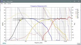
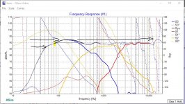
Now from 100Hz up, I have absolutely no complains with V.4. But I just want to make sure that you understand what I was trying to get at with the woofer roll-off and the effect on F3. So to be clear, there is not going to be any difference in the absolute output from the woofers. The cone and port output are not going to be affected by that impedance compensation filter on the woofers. What is at stake is its relative output compared to the rest of the speaker output.
So pic 1 shows your V.4 results and I've pointed to the difference between the general speaker level and where the woofers are rolling off and marked the approximate F3 point in yellow. Pic 2 shows my xo with the notch filter and points to the same things. And then pic 3 shows my version without the filter and shows the increase in the lower mid output and that if you set the rest of the speaker output up to that level of output, then in effect you are also raising the speaker's F3 point as well. It's still outputting down to 40'ish Hz but that output relative to the rest of the speaker is now down probably about another 3dB.
Now I just have to note that your blended woofer response is a little different than mine, I just tuned it to 50Hz, yours is down nearer to 40Hz I think which doesn't really matter too much. But I've also found that my blended woofer response is acting just a little differently than yours when I use the same values that you are using. Specifically your sims are showing less of a lower mid hump than mine is and to be honest, I'm not quite sure of the reason other than just doing the blending slightly differently. I compared our impedance results using the same values and those are identical so it's not that.
So my sims are showing just a little more need for the notch filter than yours are but regardless, you still have to live with the diminished F3. Maybe the subs can make up for that but actually your results don't show as smooth a roll-off (more shelving in other words) and that tends to not produce as flat a summing between the speakers and the subs.
So that's just in hope that you fully understand the choice you are making. It could be valid to start off that way and see what it sounds like but I'd also want to have a solution in my back pocket in the event your V.4 xo produces either a slightly weak bass sounding speaker or a slightly chesty sounding speaker. That chestiness from the extra lower mid output is definitely something though I would try to avoid in the CC.
So the next step for me after coming up with a decent xo is to see if I can refine it any more and indeed I would have been looking at the tweeter and mid shunt resistors to start off with. I put that one on the mid when I was trying to see if I could get away with just a single series cap for the mid HP filter (I couldn't) but then left it in anyways. And I agree, it's not necessary. The 1 on the tweeter though is still helping to keep the tweeter Fs sufficiently suppressed without using a notch filter so I would keep that too.
Then I checked in your V.4 if I could eliminate the 2nd inductor on the woofers, but again I found both the FR and the impedance response are better with it in in conjunction with the rest of your xo values.
Lastly, you'll find that with a 3-way mid, where you insert the 2nd order shunt inductor can also affect the response even when the values are exactly the same. In my xo I found that the response was flatter when I put it after both the series cap and the series inductor, but in your version I found the more traditional placement right after the series cap was the best. So that's well done on all of those choices.
Next I might look at the 45 degree off-axis response of the mid once again, this time looking for any anomalies below the xo point and indeed your measurement shows a bit of a dip actually right in the mid frequencies. Very often some people prefer a bit of a dip in the mids' on-axis response but here, given that your off-axis response is already showing a dip, I would definitely be aiming for a flat on-axis response so no changes to the xo in that respect.
Next I would do the same as I suggested for your rears -> plan out in the xo what you might need to do in the event the speaker sounds a little off. So too little bass? Not enough/too much mids? Too much/not enough high frequencies?
And then moving on to the CC, try just opening up your V.4 tower xo and then import the CC files into it. You'll need to add a 2nd parallel woofer and make sure you also input the new delay variables too. That should be a very good point to start from.
In terms of CC's, I found Zaph's write up on his CC here with its broad but tiny midrange emphasis instructive. And now that you have some xo sim experience under your belt, here are some xo thought from Jeff Bagby that might be helpful - Box
Also, I forgot to mention that to see the speaker current consumption, you need to also check/activate that tiny front resistor in the Curves drop down menu of that graph. I'm guessing you probably figured that out though.
Now from 100Hz up, I have absolutely no complains with V.4. But I just want to make sure that you understand what I was trying to get at with the woofer roll-off and the effect on F3. So to be clear, there is not going to be any difference in the absolute output from the woofers. The cone and port output are not going to be affected by that impedance compensation filter on the woofers. What is at stake is its relative output compared to the rest of the speaker output.
So pic 1 shows your V.4 results and I've pointed to the difference between the general speaker level and where the woofers are rolling off and marked the approximate F3 point in yellow. Pic 2 shows my xo with the notch filter and points to the same things. And then pic 3 shows my version without the filter and shows the increase in the lower mid output and that if you set the rest of the speaker output up to that level of output, then in effect you are also raising the speaker's F3 point as well. It's still outputting down to 40'ish Hz but that output relative to the rest of the speaker is now down probably about another 3dB.
Now I just have to note that your blended woofer response is a little different than mine, I just tuned it to 50Hz, yours is down nearer to 40Hz I think which doesn't really matter too much. But I've also found that my blended woofer response is acting just a little differently than yours when I use the same values that you are using. Specifically your sims are showing less of a lower mid hump than mine is and to be honest, I'm not quite sure of the reason other than just doing the blending slightly differently. I compared our impedance results using the same values and those are identical so it's not that.
So my sims are showing just a little more need for the notch filter than yours are but regardless, you still have to live with the diminished F3. Maybe the subs can make up for that but actually your results don't show as smooth a roll-off (more shelving in other words) and that tends to not produce as flat a summing between the speakers and the subs.
So that's just in hope that you fully understand the choice you are making. It could be valid to start off that way and see what it sounds like but I'd also want to have a solution in my back pocket in the event your V.4 xo produces either a slightly weak bass sounding speaker or a slightly chesty sounding speaker. That chestiness from the extra lower mid output is definitely something though I would try to avoid in the CC.
So the next step for me after coming up with a decent xo is to see if I can refine it any more and indeed I would have been looking at the tweeter and mid shunt resistors to start off with. I put that one on the mid when I was trying to see if I could get away with just a single series cap for the mid HP filter (I couldn't) but then left it in anyways. And I agree, it's not necessary. The 1 on the tweeter though is still helping to keep the tweeter Fs sufficiently suppressed without using a notch filter so I would keep that too.
Then I checked in your V.4 if I could eliminate the 2nd inductor on the woofers, but again I found both the FR and the impedance response are better with it in in conjunction with the rest of your xo values.
Lastly, you'll find that with a 3-way mid, where you insert the 2nd order shunt inductor can also affect the response even when the values are exactly the same. In my xo I found that the response was flatter when I put it after both the series cap and the series inductor, but in your version I found the more traditional placement right after the series cap was the best. So that's well done on all of those choices.
Next I might look at the 45 degree off-axis response of the mid once again, this time looking for any anomalies below the xo point and indeed your measurement shows a bit of a dip actually right in the mid frequencies. Very often some people prefer a bit of a dip in the mids' on-axis response but here, given that your off-axis response is already showing a dip, I would definitely be aiming for a flat on-axis response so no changes to the xo in that respect.
Next I would do the same as I suggested for your rears -> plan out in the xo what you might need to do in the event the speaker sounds a little off. So too little bass? Not enough/too much mids? Too much/not enough high frequencies?
And then moving on to the CC, try just opening up your V.4 tower xo and then import the CC files into it. You'll need to add a 2nd parallel woofer and make sure you also input the new delay variables too. That should be a very good point to start from.
In terms of CC's, I found Zaph's write up on his CC here with its broad but tiny midrange emphasis instructive. And now that you have some xo sim experience under your belt, here are some xo thought from Jeff Bagby that might be helpful - Box
Attachments
Yeah I have also found that your designs dont exactly work the same when I input it to my Xsim files.
I do agree that there are some differences due to our blended responses being slightly different.
That is a good point about the F3 discrepancy. But tbh I'm not terribly worried about it. I think my blended response is just off a little. Tbh I have taken note of that and will judge that when I listen to them.
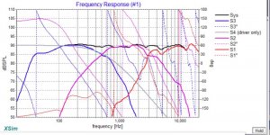
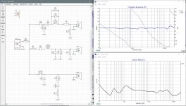
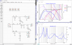
I have included a screenshot of my CC xo V1. I know it says V3, thats just cuz I was messing around before. But this is my official V1. Just putting it out there for you to see.
The system response in the midrange is not looking the best. I did do 1/6th smoothing on the mids, but that only changes the mids FR, not the system.
I also found in this design that the series notch filter worked wayyy better for the tweeter.
I do agree that there are some differences due to our blended responses being slightly different.
That is a good point about the F3 discrepancy. But tbh I'm not terribly worried about it. I think my blended response is just off a little. Tbh I have taken note of that and will judge that when I listen to them.
I have included a screenshot of my CC xo V1. I know it says V3, thats just cuz I was messing around before. But this is my official V1. Just putting it out there for you to see.
The system response in the midrange is not looking the best. I did do 1/6th smoothing on the mids, but that only changes the mids FR, not the system.
I also found in this design that the series notch filter worked wayyy better for the tweeter.
Attachments
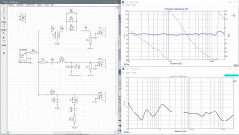
The FR looks good. I wouldn't be too concerned with some of the wiggles in the mid response, it's more or less an artifact of the measurement mic distance. Change the system curve to maybe 1/12 smoothing too. Or 1/6th. I've read that 1/6th is more or less the way we actually hear things but it doesn't hurt to start out by showing the finer details.
I think your low impedance at about 5kHz is the result of the very low value on L4. Pull up the current graph if you want to and see if their will be enough current with the HT amp and about 30W of power. Probably not a problem is my guess.
I think though that I would have tried to keep as many things as possible the same in the CC as in the towers, like the xo points for eg. And therefore there wouldn't be a need for the extra LCR filters on the mids and the woofers. Maybe see if you can't get rid of those on your next attempt.
And if the series LCR works better on the tweeter, by all means, that's the one you want to use.
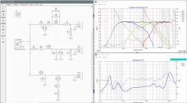
Alright so I got the CC V.2 for you!
I did start with woofer, then mid, then tweeter when I started with V1. But with these screenshots, I kinda worked backwards.
So, first off. I actually had the same xo points for the CC. But it might look a little different due to getting a good roll-off with the drivers. Like we have said, follow the natural roll-off of the drivers as well. So, I followed that as we as trying to get it as close as I can to the xo point.
First screenshot is the tweeter is what I had from V.1 but I fixed the impedance issue around 5kHz. Fyi, it was C4 and C5 that contributed to the impedance dip.
The second screenshot is my best attempt at bringing the tweeter roll-off closer to the target curve. But it just doesnt look good and it also creates a low impedance issue.
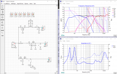
So now screenshot 3, the mid pair. The series notch filter was there to help with a peak that was happening around 3.5kHz. But I was able to work around that and omit the notch filter. Which is very nice since I am also worried about space in the CC.
**Side note --> In this design, I have been trying to incorporate some of the xo components I already have to save some money. Nothing too important.**
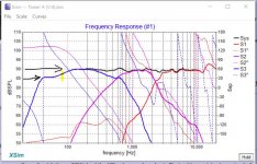
Screenshot 4 is the same thing I had from V.1 but without the series notch filter. This is purely to show why I did that before. But I now realize thats a lot of components for just a small hump. But I tried again with just the three components to fix that hump around 900Hz (Screenshot 5). I think it looks good in the low end, but it did kinda screwup the system FR in the mid-range. But honestly not terrible, only 2dB down around 1.3kHz. I had also went back to the mid pair to see if I could fill in that null, but was unsuccessful. Cant put more power where there is already a null in the FR of the mid pair. Also, I already omitted the series resistor for the mids, so there was not way to bring it up and then bend the curves more.
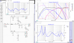
So, screenshot 6 is the final V.2 at 18W. I have also included the current graph. Screenshot 7 is V.2 with the amp at 30W. Max current is 5.15A. So, not bad.
Overall, this is looking pretty good to me, but lemme know what you think. The phase of mid and tweeter is looking good, crossing near the xo point. Impedance is good, above or right at 3ohms. I was able to get rid of 6 xo components, which is huge imo.
**I just noticed this, but I went back to the tweeter at the end and messed with it but forgot to put it back. Thats why screenshot 6 and 7 dont look as well in the high-end. But screenshot 5 is accurate for what the tweeter will be.**
Would be awesome if we can finalize this today or tomorrow so I can order the components! I have already sourced out the components for the rears and towers, and have noticed that there is a handful of them that have only like "10 left in stock". So I dont wanna miss it haha.
I did start with woofer, then mid, then tweeter when I started with V1. But with these screenshots, I kinda worked backwards.
So, first off. I actually had the same xo points for the CC. But it might look a little different due to getting a good roll-off with the drivers. Like we have said, follow the natural roll-off of the drivers as well. So, I followed that as we as trying to get it as close as I can to the xo point.
First screenshot is the tweeter is what I had from V.1 but I fixed the impedance issue around 5kHz. Fyi, it was C4 and C5 that contributed to the impedance dip.
The second screenshot is my best attempt at bringing the tweeter roll-off closer to the target curve. But it just doesnt look good and it also creates a low impedance issue.
So now screenshot 3, the mid pair. The series notch filter was there to help with a peak that was happening around 3.5kHz. But I was able to work around that and omit the notch filter. Which is very nice since I am also worried about space in the CC.
**Side note --> In this design, I have been trying to incorporate some of the xo components I already have to save some money. Nothing too important.**
Screenshot 4 is the same thing I had from V.1 but without the series notch filter. This is purely to show why I did that before. But I now realize thats a lot of components for just a small hump. But I tried again with just the three components to fix that hump around 900Hz (Screenshot 5). I think it looks good in the low end, but it did kinda screwup the system FR in the mid-range. But honestly not terrible, only 2dB down around 1.3kHz. I had also went back to the mid pair to see if I could fill in that null, but was unsuccessful. Cant put more power where there is already a null in the FR of the mid pair. Also, I already omitted the series resistor for the mids, so there was not way to bring it up and then bend the curves more.
So, screenshot 6 is the final V.2 at 18W. I have also included the current graph. Screenshot 7 is V.2 with the amp at 30W. Max current is 5.15A. So, not bad.
Overall, this is looking pretty good to me, but lemme know what you think. The phase of mid and tweeter is looking good, crossing near the xo point. Impedance is good, above or right at 3ohms. I was able to get rid of 6 xo components, which is huge imo.
**I just noticed this, but I went back to the tweeter at the end and messed with it but forgot to put it back. Thats why screenshot 6 and 7 dont look as well in the high-end. But screenshot 5 is accurate for what the tweeter will be.**
Would be awesome if we can finalize this today or tomorrow so I can order the components! I have already sourced out the components for the rears and towers, and have noticed that there is a handful of them that have only like "10 left in stock". So I dont wanna miss it haha.
Attachments
-
 CC V4 at 30W.PNG298.5 KB · Views: 68
 -
 CC V4 at 18W.PNG296.7 KB · Views: 69
 -
 CC woofer agttempt without notch filter.PNG286.6 KB · Views: 64
 -
 woofer wout notch filter.PNG268.2 KB · Views: 54
 -
 CC mids.PNG263.3 KB · Views: 61
 -
 another take at CC tweeter.PNG262.7 KB · Views: 58
 -
 CC_tweeter.PNG263.5 KB · Views: 64
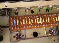
Hey also do you know where to buy the point to point wiring strip things. Picture included below, idk what they are specifically called and cannot find them on the internet. But I think this will be the easiest way to make the xo. Especially for the rears where I might need to mount some components on the side walls and the bottom.
Attachments

- Home
- Loudspeakers
- Multi-Way
- First-Timer Home Theater Speaker Build