Well, obviously I missed the ball and there is a lot more I need to get a grip of.
I guess I forgot to say that the points I picked where also not set in stone. More of a starting point and frequency area to look at.
So, I will listen this time and start with the rears haha I think you've had enough of me jumping ahead.
Just to be 100% sure on what youre looking for from me (correct me if I'm wrong).
Find a frequency range for the xo point by taking into account:
- The harmonic distortion of the drivers
- Keeping the tweeters Fs below 30dB
- Keeping the xo point below the 45deg fall of point for the woofer
- The natural roll off of the drivers
- Bad peaks in the driver's FR
- Aligning the phase of the drivers at the xo region
Is there anything I'm missing?
Also, is there something in XSim where I can just apply a filter to the drivers instead of changing component values every time? Just to start off to see the responses being filtered.
Hey no worries. I appreciate that different people learn in different ways.
Your list looks good. Actually I had to do a palm to the forehead just a few minute ago because I suddenly realized that I forgot 1 of the fundamental rules myself. Doh!!
Your xo frequency should be equal to or less than the equivalent wavelength of the distance of the center to center spacing of your drivers. Better yet if it's equal to or less than 1/2 of that wavelength and best case scenario is equal to or less than 1/4 of the wavelength.
So for your rears, the center to center spacing between drivers is 5.5". That wavelength corresponds to a frequency of 2455Hz. So according to this rule, that should be about the upper limit of the xo frequency. Better yet if it was half of that, so about 1227Hz and better still at half of that, so about 613Hz. Perhaps you can see that the more stringent versions of this rule of thumb don't get met very often unless you are using physically very small drivers or unless you are using a coaxial driver or a full range driver that doesn't need a xo at all up in the higher frequencies.
The consequences of too large a distance between drivers in relation to the xo point then is lobing in either the vertical or horizontal planes depending on driver orientation, creating uneven off-axis responses in other words. In truth I perhaps see this rule of thumb broken by more professional builders than any other but still, it's something to keep in mind.
When I 1st started using XSim, there was a way to create textbook filters as a block, but I can't seem to figure out how to do that now. I haven't bothered to do xo work in that fashion in a long time. Instead I drop in the necessary components for the filter I want and then start working with the values watching what the FR of the driver does in response. This is for me the essence of xo design. When you work it this way, always start with the first series component in the filter and try to have it do as much of the work shaping the FR towards your target curve as possible before moving on the the 2nd parallel component. If there's a 3rd component (in series again) for example on the tweeter, I set it at a large value to start off with (so very little effect on the response) and try to have the 1st 2 components doing most of the work. Sometimes just the first 2 components can get the response pretty much where you want it but with the phase out of alignment and this 3rd component can be used just more or less used for tweaking that final aspect of phase alignment. Sometimes.
However when I was just starting out with PCD, that program had a tab that will calculate the values for stock filters. As a starting point, some of them were useful although I don't thing any of them didn't require the values to be changed afterwards. But if this might help you, you can open up PCD as well and just refer to that page if you want the program to calculate some values for you to start with and then transfer those values to your XSim components.
Again though, this is one of those things where just doing the work is necessary to learning. It doesn't matter if it's right or not. In fact there's lots to be learned from making mistakes here too. Post what you come up with or if you get stuck on something or have questions, post those too and I can then give you specific feedback on what ever happens to be important.
Oh wow, that is one of THE rules that I knew as well and have also forgot haha oops!! Thats exactly the reason I tucked the mids closer to the tweeter.
But sounds good! Ill get on that today and hopefully have something to post by the end of today!
Correction: I placed the mids so close to the tweeter for just driver placement sake for the off-axis phase. Where "the combined response for two identical drivers will be largely uncolored up to that frequency where the driver spacing equals half the wavelength." (John L. Murphy)
Last edited:
Do you mind expanding on your Harmonic Distortion explanation?
I get what youre trying to say, but Im not understanding what to actually look for too start. Like, why did you choose the 3rd harmonic as the only one to take a look at for the xo point? Why not F5 as well since that one was not flat?
Basically, I get where to go with this but not how to start. Which harmonics do I pay attention to and why?
Even order harmonics are the same note as the source, so aren't so bad.
Odd order harmonics are a different note altogether and so are less acceptable.
Generally the overall shape of the 5th order usually matches the 3rd order pretty closely.
And as the orders increase, the SPL level generally decreases, thus making the 3rd harmonic usually the worst of the lot.
But you are not looking for flat here. You are simply looking to minimize the worst stuff (F3, usually) as much as possible from each driver and therefore across the whole frequency range of the speaker. The different distortions will still vary with frequency but you will have at least tried to get the best out of each driver as possible. So it behooves you to look at F3 especially for each driver when choosing where to cross.
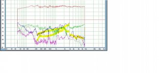
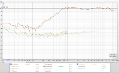
So again referring back to my example, the F3 in the woofer is higher than the F3 in the tweeter once you start going above about 1500Hz regardless of the fact that neither one of them are flat. Pics are below again. In pic 3 I've spliced them together at about 1500Hz. And then pic 4 is if you use a 3kHz splicing point. And you should see that in that important midrange region from 1500-3000Hz, the speaker with the lower xo point is going to probably sound better because of the lower 3rd order (and 5th too) harmonic distortion in the midrange.
Not an exact representation of course, because when you add in your xo components, the different orders of distortion are also going to roll-off in the same manner as the fundamental 40 or 50 or whatever dB it is above the distortion.
At the same time we have to ask if 1500Hz is too low for this tweeter? And the answer for a 2-way speaker that won't be playing too loud, maybe even for a 3-way that can play a little bit louder is probably no. This isn't a little 1/2" or 3/4" tweeter. It's just over 1" and is meant to take some power. Look at the spec sheet - power handling is 80 watts and the suggested usable frequency range is 1400-20,000Hz, although I usually take that last one with just a touch of salt. Our primary concern then is that Fs stays reasonably low and for that to happen a steeper slope or perhaps a notch filter or both would be necessary.
But let's not make the decision beforehand. Let's work the xo into multiple versions and see what looks best. Even better would be to then choose the best looking xo's and listen to them and see what sounds best to your ears but that's something that might require more time than you have as well as a decent supply of xo parts on hand to experiment with. Maybe you might want to do that for the fronts but I wouldn't sweat the surrounds too much in all honesty.
Odd order harmonics are a different note altogether and so are less acceptable.
Generally the overall shape of the 5th order usually matches the 3rd order pretty closely.
And as the orders increase, the SPL level generally decreases, thus making the 3rd harmonic usually the worst of the lot.
But you are not looking for flat here. You are simply looking to minimize the worst stuff (F3, usually) as much as possible from each driver and therefore across the whole frequency range of the speaker. The different distortions will still vary with frequency but you will have at least tried to get the best out of each driver as possible. So it behooves you to look at F3 especially for each driver when choosing where to cross.
So again referring back to my example, the F3 in the woofer is higher than the F3 in the tweeter once you start going above about 1500Hz regardless of the fact that neither one of them are flat. Pics are below again. In pic 3 I've spliced them together at about 1500Hz. And then pic 4 is if you use a 3kHz splicing point. And you should see that in that important midrange region from 1500-3000Hz, the speaker with the lower xo point is going to probably sound better because of the lower 3rd order (and 5th too) harmonic distortion in the midrange.
Not an exact representation of course, because when you add in your xo components, the different orders of distortion are also going to roll-off in the same manner as the fundamental 40 or 50 or whatever dB it is above the distortion.
At the same time we have to ask if 1500Hz is too low for this tweeter? And the answer for a 2-way speaker that won't be playing too loud, maybe even for a 3-way that can play a little bit louder is probably no. This isn't a little 1/2" or 3/4" tweeter. It's just over 1" and is meant to take some power. Look at the spec sheet - power handling is 80 watts and the suggested usable frequency range is 1400-20,000Hz, although I usually take that last one with just a touch of salt. Our primary concern then is that Fs stays reasonably low and for that to happen a steeper slope or perhaps a notch filter or both would be necessary.
But let's not make the decision beforehand. Let's work the xo into multiple versions and see what looks best. Even better would be to then choose the best looking xo's and listen to them and see what sounds best to your ears but that's something that might require more time than you have as well as a decent supply of xo parts on hand to experiment with. Maybe you might want to do that for the fronts but I wouldn't sweat the surrounds too much in all honesty.
Attachments

That makes much more sense thank you!
So I'll post this now since I already looked at it.
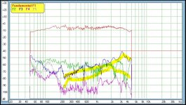
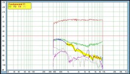
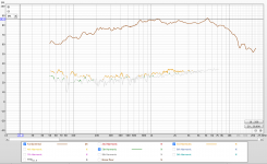
Fyi, distortion graphs for both Rear A and B where practically identical, so I'm just including Rear A.
So, while looking at the harmonic distortion of the rears they both have a relatively flat response which I remember you saying earlier that they might. Also, they both juggle around 30dB, so both close to each other. My only thought is that your example had F3 down near -60dB while these are around 30dB, dont know if that is something worth stressing about or not.
But to me, as far as the harmonic distortion goes, it would be adequate to crossover anywhere after 1kHz.
Screenshot 1: The tweeter
Screenshot 2: The woofer
So I'll post this now since I already looked at it.
Fyi, distortion graphs for both Rear A and B where practically identical, so I'm just including Rear A.
So, while looking at the harmonic distortion of the rears they both have a relatively flat response which I remember you saying earlier that they might. Also, they both juggle around 30dB, so both close to each other. My only thought is that your example had F3 down near -60dB while these are around 30dB, dont know if that is something worth stressing about or not.
But to me, as far as the harmonic distortion goes, it would be adequate to crossover anywhere after 1kHz.
Screenshot 1: The tweeter
Screenshot 2: The woofer
Attachments
Last edited:
Oh great the windows side of my Mac is updating and literally tells me that “This will take a while”.
So unfortunately probably cant get back to you on the XSim stuff by today.
So unfortunately probably cant get back to you on the XSim stuff by today.
The fundamentals are up close to 90dB. The harmonic distortion levels are down around 30dB. The difference equals about -60dB. So that checks out.
And this is why we measure - quite a difference from the earlier versions of those drivers I used in my example. So I agree with your conclusion - harmonic distortion isn't going to make much of a difference for the xo point for these 2 drivers. Both of them are operating in a pretty similar clean range in the frequencies we are looking at. Maybe they'll be more intermodulation distortion in the woofer because of its greater cone excursion at higher output levels but I'm not inclined to sweat that one here.
And this is why we measure - quite a difference from the earlier versions of those drivers I used in my example. So I agree with your conclusion - harmonic distortion isn't going to make much of a difference for the xo point for these 2 drivers. Both of them are operating in a pretty similar clean range in the frequencies we are looking at. Maybe they'll be more intermodulation distortion in the woofer because of its greater cone excursion at higher output levels but I'm not inclined to sweat that one here.
Oh that is right!
Awesome
So, I've been doing some research and reading. But I cant seem to find a good reference in how to start with the values for either the capacitor or the inductor.
Usually in school we had a value given for us for one of the values for filter stuff. But, it seems like I cant just pick any value for a cap and then do the math for the inductor. Seems like I need to pick a ballpark value for the cap and then go from there, but I cant find anywhere that explain how to initially start.
Any suggestions?
Btw, I know the circuit that will be used, as well as keeping in mind the correct dampening for the LR filter. But essentially, how do I start pick the first component value and why?
Thanks!
Update:
I found in the LDC these calculations for a Second-Order Linkwitz-Riley filter:
C1&2 = .0796/(R_H*f)
L1&2 = (.3183*R_L)/f
R_H = tweeter impedance
R_L = woofers impedance
Is this what you use?
Last edited:
Try this - completely ignore any xo calculations!! Seriously. You don't need any of them.
I've never used a single one. In fact as I work through a xo, I rarely even look at what the values of the components I'm working with are until towards the end. I just spin the wheel on my mouse and stop when the FR starts getting close to the target curve. Then I move on the to the next component. Probably come back to the 1st one again and adjust it. And then maybe the 2nd one too. Then I move on to the next driver and do the same. Then I start looking at the summed response and the impedance and the phase and start tweaking again to get those looking as best I can.
All of that textbook xo stuff was useful and perhaps needed in the past but with these newer xo programs, that need is almost obsolete. Just let the program do the work for you. Play around with values until you start to understand their effect in the different circuit placements and/or until you get a result you like. That's it.
I do have a methodology and a couple of simple rules of thumb that I follow as I work towards my xo design goals though. Give me just a little time to write something up but in the meantime, just sort of pretend XSim is a game and start playing with it. It doesn't matter if it's right or wrong to start off with. It's just about learning how to use it and the main cause and effects relationships of the components in their possible different configurations.
Wow that is actually a really good point that I would have never thought of haha. I've always stuck to the calculations!
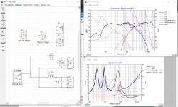
So I did what you said, just played around with it and the best I got was the screenshot attached.
A few things.
- I could not line up the phase and get the System response to be flat. The tweeters phase just did not want to move close to the target. I could lower the woofers phase down to where the tweeter is, but then the system FR looked pretty bad.
- The tweeters Fs is at about 65dB. So not even close to 30dB. Possibly might have to do a third or fourth order.
- I do not know how to take into account the impedance graph. Basically right now I tried to make that system peak in the middle not crazy high. But other than that I dont know what I'm looking for there.
Just a clarification, this is not by any means "the best work I can do". I spent 5 minutes on this just to get a feel for it like you said and wanted to shoot it to you because I have to go help the fam now.
I'll be looking forward to your methodology and rules of thumb!
Attachments
OK so here's a quick response before I write up something longer.
That's actually not half bad.
Re your questions:
- With 2 x 2nd order electrical, you've pretty much hit your target curves but you can't get your phase to line up. So add a 2nd series cap (3rd order) on the tweeter and adjust it mostly for the purposes of phase alignment.
- So 2nd order at 2500Hz means that tweeter Fs is still too high. So either you move the xo point lower, increase the slope or target the Fs with an impedance compensation filter, which is just another name for an LCR notch filter. Try a series filter placed in parallel. But I'll admit, figuring notch filter values on your own is a little difficult. That may need a separate tutorial or go to the PCD calculator in this instance and then start with those suggested values and adjust as necessary.
- there is really just 1 main thing to be mostly concerned about with impedance and that's that it doesn't go too low for your amplifier. Don't worry about what it's doing up high in other words, just down in the lower impedance numbers. And 2ohm at about 4kHz is in fact too low. One other thing you need to maybe also look at is the impedance phase. If it's dropping down below -60 degrees that could also be trouble, especially if the impedance is low in the same range. The same holds true at +60 degrees.
Besides what I already mentioned, here's my quick critique:
- C1 is too large and L1 is too small. This is in fact the reason that your impedance around 4k is going too low. As I mentioned before, try and get the first component in the network to do most of the work. In electrical terms, C1 is letting too much of the signal through and then L1 is passing too much of the signal to ground. And of course, if too much of the signal is going to ground it's called a....... wait for it... a short. Thus your dangerously low impedance in that frequency range.
- I'd also say your tweeter is running a little too hot still. Add in a series resistor either before the filter or after it or both or an L-pad just before the driver. Each of those attenuates the tweeter level but does so in a slightly different way. Which one is going to be most advantageous to this particular situation is only going to be revealed through trial and error.
Also to note:
- Just going with a 2nd order on the woofer means you've got minor problems with the midrange peak and following trough. They are still within plus or minus 3dB so that's why I say minor. You may wish to try a lower value on L2 and attach the mid peak with a notch filter. It's worth it as a learning exercise although in truth, I think I'd be trying to limit my xo part count for these surround speakers.
- The only other thing that might be a problem here is the woofer's resonance peak at about 5Khz which is only down about 15dB from the fundamental. And it's such an easy thing to fix. Add a small value capacitor in parallel with L2. Adjust until it hits that peak and observe the results. I call this a tanking circuit and it's just a variation on a notch filter, this time a parallel LCR wired in series with the driver but without the R component. And here's where you start to get into some of the possible elegance of xo design because L2 is pulling double duty -> it's acting as the 1st component in the 2nd order LP filter and it's working as 1 of the components in an LC(R) notch filter both at the same time. That's lovely.
Last edited:
I've actually had a little bit of a rough day today and I've kind of run of of brain juice. 
I hope you won't mind if I wait until tomorrow to write you up something in a little more detail.
In the mean time, keep playing around with XSim though if you wish, all of it is a learning exercise. Go back into Response Modeler if you need to to create new target curves. It'll be up in the 1st module of the program under the "High Pass" and "Low Pass" sections. I spent a little time one day and created a folder of Filters and just created a number of useful HP and LP filters, LR2 and LR4, plus HP and LP filters together for midranges in 3-ways so I had easy access to them for future reference purposes. You might want to do something similar as you play around with your speaker xo's. Or not. 😉 Totally up to you.
Re textbook xo calculators, they are actually a fairly old school way of doing things and maybe they serve some purpose but I don't recommend them because the new xo simulation programs make them mostly unnecessary but also because they are not actually very accurate.
The problem is that neither a driver's impedance nor its frequency response are flat which means the results are unlikely to be as expected. In order to produce something more accurate, one used to have to fix (ie. flatten) the impedance first by using a Zobel or an impedance compensation notch filter or both but that just adds components that aren't necessarily needed just so your calculated values produce more predictable results and even then they still won't account for a driver's natural roll-off combining with the roll-off produced by the xo filters. Thus, not so accurate.
But the programs give you accurate real time results of what each component does to both the FR and the impedance and more too. So that's really the way to go.
When I was starting out, I found it very helpful to write up a page or 2 listing the xo components both in series and in parallel and their possible combinations with little diagrams showing their effect on the FR and I might suggest the same for you if you are unsure about how some of them work. In essence you are creating a toolbox for your self that you can reach into to solve the different types of problems you might encounter in your xo sims. Because the bigger your tool kit, the better xo's you are likely able to put together.
So besides the standard HP and LP components and configurations, there are things like a Zobel (though I pretty much never use them unless they are absolutely necessary), series and parallel notch filters, what I refer to as tanking filters (at least 4 variations), HP and LP shelving filters, resistor attenuation in series either before or after the xo or with an L-pad (each one produces a slightly different result), resistors added to a shunt (parallel) line and a resistor just placed on its own in parallel before the driver. Doesn't hurt to know what some of those do to the impedance as well. And phase too.
I'll try to hit on most of these as we go further along with the xo work.
No worries on the delay! I'm busy this weekend too so I dont have too much time until Monday to work on the sims.
But thank you for all that, that is all so helpful!
Getting closer and closer😀
Also, how L2 is doing double duty.. that is so cool!!
But thank you for all that, that is all so helpful!
Getting closer and closer😀
Also, how L2 is doing double duty.. that is so cool!!
Ok that's good because this is taking me longer than expected. Looks like I won't have it finished until tomorrow.
Sounds good!
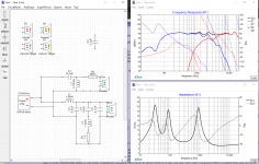
So here is the new rendition taking your points into account.
I kept the impedance around 4ohms to keep it safe and tried balancing that FR more.
In terms of phase, it seems like I still couldnt quite get it there. But you did say if I were to flip the polarity of one of the drivers and there then produces a wide and deep null near the xo point, then that also indicates good phasing. Which is what happened when I flipped the tweeters polarity!
I couldnt get that small valley around 1.8kHz to smooth out. Possibly with more components we can, but again this is just the rears. And it's only like 2dB.
The peaks and valleys are all within 2dB from the fundamental.
Also, the impedance phase I tried keeping within the +/-60dB like you said. Idk if that the only criteria I should follow with impedance phase or not.
I did forget to focus on the tweeter Fs tho to make sure its way down. Oops, that is something Ill try to tackle again.
That is true about textbook calculations. Since the driver is not a fixed impedance, it always felt wrong running the calculations and putting 8ohms into the equation. Do you think it's needed to put in an impedance compensation filter on these or no?
Anyways, I hope it's looking pretty good to you for the rears (minus the tweeters Fs). Personally it looks pretty good. A little too many components than I would have liked, but they really did balance it out much better.
FYI, I do not have crossover components lying around for testing. So, I more or less want to get these sims pretty darn good and then test by ear for any small tweaks that might need to be done. In my experience, xo components are pretty expensive and I dont have the money to buy a lot or variations and test out them all. So for me, getting the base xo built and then if tweaks need to be made, then I can do that once.
I hope that made sense^ haha
Attachments
Last edited:
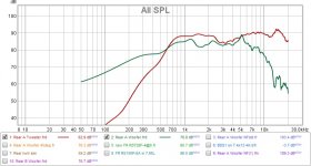
First thing to check is your tweeter file. Something doesn't look right to me. From your REW file for rear A, the tweeter level is up at about 90dB and the woofer level down at about 300Hz is at about 77dB (attached). It's not quite possible to attenuate the tweeter 13dB with a .3ohm series resistor so either your file or mine is out of whack.
Re the xo:
- in terms of FR, it looks smooth enough but I'm concerned with those 2 peaks. Not that they exist but that they are too high in SPL compared to everything else. In the plus and minus game, peaks tend to be worse on the ears than the dips so better to err on the minus side instead of the plus.
- this may be something that you only learn through experience, or perhaps the calculators would show something similar, but you still have L1 doing most of the work on your tweeter xo. That 1st series cap of almost 15uF is hardly doing anything when it should be shouldering as much of the load as it can. Down in the neighborhood of probably 4-8uF is where you should probably be playing for a 2nd order filter and a 2500Hz xo point.
- speaking of, the xo point is up around 3000Hz which I think is a little too high. I've been shooting for something between 2-2.5kHz with 1 version even exploring a xo down at about 1400Hz.
- impedance is good
- phase alignment was better I think in the 1st version. A word of caution on the reverse null -> phase can actually be fairly poorly aligned and yet cross each other right at or near the xo point which means that with polarity flipped, you will get a null, possibly even fairly deep but more than likely quite narrow. This is better than no null at all but it still may not mean that the phase is well aligned in the xo region. Better is deep and wide if you are going to use the reverse null as a phase alignment indicator but it's better to just look at the phase traces themselves and see how well they are matching.
- you can also see that the tweeter level at about 2000Hz is barely below the woofer level so the 2 responses should be combining to produce some higher output and yet they are not. Because -> phase is not well aligned there. Chances are good therefore that when you move off-axis and the phase differences shift, that sum off higher output is likely to appear in the off-axis responses. Not ideal. Especially in the critical midrange zone.
- definitely a good exercise to try a secondary approach to the woofer xo, so a lower L2 value coupled with an LCR that attacks the mid peak, but I wouldn't have tried that until I'd exhausted my attempts with the 1st method. Regardless, see if you can't work those LCR values a little more to reduce that 1st peak at about 1200Hz.
- just in case -> capacitors wired in parallel sum their values. So although you've got the LCR in between them, C2 and C5 are essentially just wired in parallel. Nothing wrong with that really, often you need to combine more than 1 cap in parallel to produce a value that you need, but it's not really necessary here in the sim. Try shorting C5 and changing C2 to 11.5uF -> should be pretty much the same result. Could be there is some tiny difference because of the LCR in between, I didn't try it and I don't have an electronics background to know for sure, but I doubt it's anything significant.
Attachments
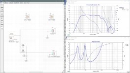
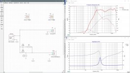
So here’s the step by step procedure of how I basically go about working on a 2-way xo. I encourage you to open your own copy of XSim and follow along but your going to have to figure out your tweeter file to start off with.
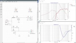
- Start with the woofer. You’ve already set your target curve at about the same level as the driver’s level at about 200Hz. If you want to make life maybe a little easier for yourself, just display the woofer and the target curve. If you want to have a look at what your xo components are also doing to the impedance, you’ll need to take the tweeter out of the equation. So just pull the connection to ground off the driver and that will do the trick. Pic 1
- Drop in a series inductor and change its value until you’ve got a decent match to the roll-off (or knee) of your target curve because this is what the 1st series component does – it determines where in the frequency range the roll-off is going to start. And you want for this 1st series component to do as much of the work as possible. I stopped at a value of 2.7 mH and we are actually pretty close to the target curve already. Pic 2. As I’m sure you know, you also have to be concerned with the resistance of inductors. So just note that XSim automatically sets the inductor R value at .35ohm which is fine for now. You can adjust these later as you look at the real world parts that you are going to be using.
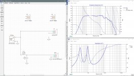
- Now drop in your 2nd component, the parallel capacitor and note how it changes the response as you change up its value – primarily it is increasing the roll-off below the knee that you set with the inductor. Note however that as it gets larger in value, you will usually actually see an increase in the response just above the knee. Sometimes you can make use of this but usually it’s an indication that you’ve gone too far with that second component. As a rule of thumb, I try to keep the values of the capacitor going to ground as small as possible. Too large and your impedance may drop too low the same way it did with your tweeter in your 1st attempt. Here I’ve got a pretty good match to the target curve with a value of 6.2uF. Note that the roll-off actually exceeds the target curve as you go higher in frequency which can actually be a good thing. Pic 3
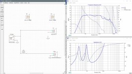
- Note that with that cap value, there was a tiny bit of increase up around the knee so now I go back to L1 and increase it just a touch as necessary, up to 3mH now. Pic 4.
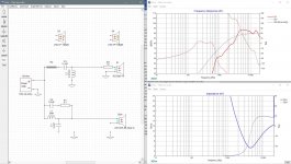
- We can look at our result and note that we aren’t getting the smoothest of responses between about 200 and 2000Hz but it’s not actually too bad for a surround speaker. For a speaker that was going to be used in perhaps a more critical listening situation I might try to flatten it out a bit more by moving the xo point lower or by trying to tame the mid peak with a notch filter. Up to you what you want do here and how many parts you want to throw at it. One rule of thumb to note is that dips or valleys are always easier on the ears than peaks so you want to keep that in mind when you are working with a response that isn’t quite flat.
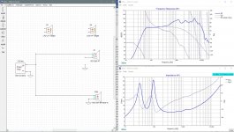
- The only other thing to note is the driver’s resonance peak at about 5kHz which is only about 13dB down from the fundamental. So let’s hit that with a tanking filter. Add a cap in parallel with L1 and adjust until it hits the peak. I used .3uF. Again note the effects. The peak is well taken care of but the roll-off is affected too - positively below the peak and negatively above it. Pic 5.
- So you might again try readjusting your LP filter values but I didn’t find here that any changes produced better results so I left them the same. Note that L1 and C1 work together to position that tanking notch so that if you change 1 you probably need to change the other one too. Depends on the size of the changes though.
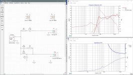
- Now at this juncture, it’s possible to already see that if you just want to keep the xo as simple as possible and accept some wiggle in the FR (ie. you are not going to treat the mid peak with a notch filter), then the 2500Hz target is probably a little too high here because we can’t raise the actual FR of the woofer up to the target curve without also raising that mid peak up as well. And that’s something which is not really a very good idea. So you can either create and then import a new target curve for the tweeter probably somewhere between 2000-2200Hz or you can just eyeball it with the 2500Hz curve and aim a little to the left of it as you work with that driver.
- Ok, almost done with the woofer now but I’d be remiss if I didn’t finally note that the tanking filter as used here can potentially cause you low impedance problems so it may be a good idea to decrease the depth of the 5K notch by adding a small resistor in series with C2. A 5ohm resistor brings the level of the peak down about 30dB from the fundamental which is fine. And now the woofer is done until we fine tune it after doing the tweeter. Last pic.
- Start with the woofer. You’ve already set your target curve at about the same level as the driver’s level at about 200Hz. If you want to make life maybe a little easier for yourself, just display the woofer and the target curve. If you want to have a look at what your xo components are also doing to the impedance, you’ll need to take the tweeter out of the equation. So just pull the connection to ground off the driver and that will do the trick. Pic 1
- Drop in a series inductor and change its value until you’ve got a decent match to the roll-off (or knee) of your target curve because this is what the 1st series component does – it determines where in the frequency range the roll-off is going to start. And you want for this 1st series component to do as much of the work as possible. I stopped at a value of 2.7 mH and we are actually pretty close to the target curve already. Pic 2. As I’m sure you know, you also have to be concerned with the resistance of inductors. So just note that XSim automatically sets the inductor R value at .35ohm which is fine for now. You can adjust these later as you look at the real world parts that you are going to be using.
- Now drop in your 2nd component, the parallel capacitor and note how it changes the response as you change up its value – primarily it is increasing the roll-off below the knee that you set with the inductor. Note however that as it gets larger in value, you will usually actually see an increase in the response just above the knee. Sometimes you can make use of this but usually it’s an indication that you’ve gone too far with that second component. As a rule of thumb, I try to keep the values of the capacitor going to ground as small as possible. Too large and your impedance may drop too low the same way it did with your tweeter in your 1st attempt. Here I’ve got a pretty good match to the target curve with a value of 6.2uF. Note that the roll-off actually exceeds the target curve as you go higher in frequency which can actually be a good thing. Pic 3
- Note that with that cap value, there was a tiny bit of increase up around the knee so now I go back to L1 and increase it just a touch as necessary, up to 3mH now. Pic 4.
- We can look at our result and note that we aren’t getting the smoothest of responses between about 200 and 2000Hz but it’s not actually too bad for a surround speaker. For a speaker that was going to be used in perhaps a more critical listening situation I might try to flatten it out a bit more by moving the xo point lower or by trying to tame the mid peak with a notch filter. Up to you what you want do here and how many parts you want to throw at it. One rule of thumb to note is that dips or valleys are always easier on the ears than peaks so you want to keep that in mind when you are working with a response that isn’t quite flat.
- The only other thing to note is the driver’s resonance peak at about 5kHz which is only about 13dB down from the fundamental. So let’s hit that with a tanking filter. Add a cap in parallel with L1 and adjust until it hits the peak. I used .3uF. Again note the effects. The peak is well taken care of but the roll-off is affected too - positively below the peak and negatively above it. Pic 5.
- So you might again try readjusting your LP filter values but I didn’t find here that any changes produced better results so I left them the same. Note that L1 and C1 work together to position that tanking notch so that if you change 1 you probably need to change the other one too. Depends on the size of the changes though.
- Now at this juncture, it’s possible to already see that if you just want to keep the xo as simple as possible and accept some wiggle in the FR (ie. you are not going to treat the mid peak with a notch filter), then the 2500Hz target is probably a little too high here because we can’t raise the actual FR of the woofer up to the target curve without also raising that mid peak up as well. And that’s something which is not really a very good idea. So you can either create and then import a new target curve for the tweeter probably somewhere between 2000-2200Hz or you can just eyeball it with the 2500Hz curve and aim a little to the left of it as you work with that driver.
- Ok, almost done with the woofer now but I’d be remiss if I didn’t finally note that the tanking filter as used here can potentially cause you low impedance problems so it may be a good idea to decrease the depth of the 5K notch by adding a small resistor in series with C2. A 5ohm resistor brings the level of the peak down about 30dB from the fundamental which is fine. And now the woofer is done until we fine tune it after doing the tweeter. Last pic.
Attachments


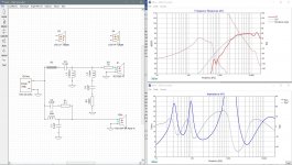
On to the tweeter.
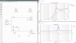
- If you want, you can do the same as with the woofer and just display the tweeter and its target curve to start off with, and to observe impedance changes, this time disconnect both the woofer lines to ground. Note that I have decided to use a new target curve –> LR2 at 2100Hz. Pic 1.
- First thing to do is to bring the tweeter level down to your target level so just throw in a resistor in series at the start of the circuit. 12ohm looks good. Doesn’t have to be perfect here, just something to get you into the ball park. Pic 2. You could also use an L-pad here just before the driver, so both a series and a parallel resistor but the single series resistor is just simpler to start off with. Try both if you want to and note any differences in the result if there are any but I don’t think the differences are as visible without the other xo components in the circuit.
- Now add in the 1st series capacitor and start to lower its value. Now with this tweeter’s dip at about 3kHz, we can’t really roll-off the lower frequencies without also bringing that 3K dip down below the target curve as well so this is going to be a little hard to choose a starting value. Let’s go with about 5uF because again we are trying to get this component to do the majority of the work. Pic 3.
- Next add in the parallel inductor. About .27mH gets a decent match to the target curve now in the lower frequencies. Like with the woofer, the tail end of the roll-off exceeds the target curve which is fine. Pic 4
- But to be honest, I’m not liking the response much at all. That dip/suck out around 3kHz is too much. So time to try something different. As I said before, where you place the series resistor or perhaps an L-pad instead can produce different results, so let’s try a series resistor after the filter now and see what that looks like. So short R2 and then add in a new resistor just before the driver. Something around 12ohms again should in theory be about right so let’s set it there even though that’s not really looking very good either. Pic 5
- But we haven’t tried changing the filter values yet so let’s try that next. Let’s repeat the process from above, so disconnect the ground connection to L2 and see what C3 alone looks like first. Still that suck out at 3K so not much difference so let’s leave it at about 5uF. Now re-connect L2. The roll-off is exceeding our target so let’s increase the value here and how about that? By about .62mH, the response has smoothed out and we are much closer to the target curve and a larger value is always preferred here if possible. A little increase to R3 now, up to about 15ohm and now you are looking excellent on the tweeter too. Not perfect yet but much better that before. Pic 6
- So note in particular how the position of that series resistor can interact with that 2nd order inductor in parallel to create very different results. It’s quite dramatic in this example actually. Again this is a real advantage to these simulation programs because I don’t think any kind of xo calculations are going to be able to predict these kinds of results.
- Like with the woofer, the last problem with the tweeter is the level of its Fs. Still too high at only about 20dB down from the fundamental. You could go with a steeper slope or you could go with a notch filter aimed at the tweeter Fs. Let’s try the notch filter 1st which in this situation will typically be a series filter attached in parallel. These are admittedly a little more difficult to find the values for and because I’m running out of time today, I’m just going to give them to you now and follow up with a more detailed explanation later. Let’s try 1.8mH for the inductor, 24uF for the cap and .5ohm for the resistor and that now puts the 800Hz Fs down about 30dB. Pic 7. Not the best actually because frequencies right next to Fs are still up a little higher but not too bad at this point.
- Your tweeter response is following the 2nd order target curve to start with and then actually exceeding it as it rolls off further but I think the same was true for the woofer so let’s look at the summed response now before we go any further. And that kind of roll-off behavior is actually a good thing -> keeping the good stuff in the passband and pushing the poorer stuff down lower when you don’t need it any more.
Attachments

- Home
- Loudspeakers
- Multi-Way
- First-Timer Home Theater Speaker Build