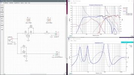
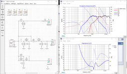
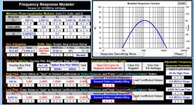
- So re-connect your woofer to ground, turn on the system curve and the woofer curve with phase and since your target curves have done their job, you can turn those off now. And voila. Pic 1
- That’s actually better than I expected. Normally I would expect to have to play with a few of the values to tweak it a bit more or maybe add 1 or 2 more, but not really necessary here. The FR isn’t the smoothest but it isn’t too bad either for this speaker. Obviously the suckout at about 1600Hz is the biggest drawback with this topology but phase tracking is quite good with a wide and deep reverse null (invert the driver polarity and press ‘hold’, bottom right of the FR graph to display it at the same time as the rest), resonances are more or less taken care of and impedance stays above 4.8ohms with the negative there being the low impedance phase at about 1900Hz. Considering the impedance around that frequency is nowhere close to being a problem, ie. it’s quite high, I would consider this a possible candidate. And the parts count isn’t too high either.
- At this point I’m going to make a few comparisons and see if I can improve anything.
- First I’m going to try an L-pad instead of just the single series resistor after the xo. You could go to an L-pad calculator if you wanted to or just play around with the different values. But right away I can see that the shape of the tweeter response is changing in an undesirable way, so I’m going to pass on that one.
- Next, I’ll look at whether some combination of a series resistor both before and after the xo might help. And again right away I can see that it doesn’t. Try these last 2 for yourself as I haven’t included any pics.
- So that’s pretty much done. Delete that old series resistor before the xo and then save the file.
Attachments
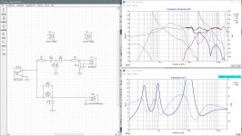
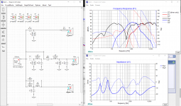
So just because I can’t help myself and because I’m wondering if I might be able to improve the tweeter Fs level and maybe that mid suckout and because I want to introduce you to a couple more things, I went ahead and tried 3rd order on the tweeter. And because I’m familiar with this little trick, I made that 2nd series cap pull double duty by adding a parallel inductor, L3, to it. It can work particularly well when that 2nd cap doesn’t need to be a small value.
Next I needed to just tweak the value of a few parts a tiny bit to optimize everything again. What’s interesting to note here is that I managed to keep the notch filter L and C values exactly the same in this version as the 1st version but just placed differently, but this version does a little bit better job at attenuating it. And I dispensed with R4, not that a single resistor is going to be saving you the big bucks.
I think the mid suckout is also decreased just a tiny bit too but it is at the expense of some output higher up around 4kHz on the tweeter. So a trade off. Up to you which one is better, but I would probably side with this 2nd one. Maybe.
Next up, now I would move on to your second version with an LCR on that mid peak and see if that type of approach may do any better job with the FR and not have to use too many extra parts to do it.
Attachments
Thank you so much Chris!!!
I will post questions when I come across them. I will get back to you on this tomorrow. Today has been filled already.
I will post questions when I come across them. I will get back to you on this tomorrow. Today has been filled already.
My oh my how plans change.
On the 8th I was busy trying to finish up my bands mixes in order to get it to our mastering engineer (which btw marks a year since I started this thread!) But, that night I was taken to the ER with terrible abdominal pain. Finally got back from the hospital last night, with a missing appendix. Haha oh how life throws ya curve balls.
Anyways, I hope you're doing better than I am!! Idk when I'll get back to you on the sims. I cant put much of a real date on that, which is all good. So for now, I'll get back on the sims when I do them haha possibly next week.
Well, that's a bit more of an exciting week than mine was!! 😱😱
Number one priority is to take care of your health. Just rest and recuperate until you feel better. Mind you as you do that, you have a perfect opportunity to spend time on the computer and do some xo sims. Kidding. Sort of. 😛
No hurry at all on my part. I'll be here whenever you're ready to carry on. Hope the mixes sounded good.
Alright! I got back to it.
For one, yeah I actually had the 'mod sensitivity' way down on the tweeter, must have been messing around with it and forgot to change it. So that's where the discrepancy in the tweeter response comes from.
Thank you again for the detailed 'tutorial'! Very helpful. I did go thru it all and did it on my own and observed while referencing yours. Haha dont want it to seem like I "copied and pasted".
But this is looking pretty good to me for a rear!
The impedance is not too low, and where the phase is below 60deg, like you said the impedance is so high there.
I was shooting to crossover around 2kHz. That valley near the xo point is not very desirable, but I can 100% live with it for the rears. Also, the valley near 500Hz is something to note, but I did not incorporate the port into the woofer blended response and judging by yours, it doesnt bother me that much.
In my circuit, R2 did not make much sense to me. I know you said a tanking filter can cause impedance issues, but I didnt see any change at all with or without that resistor. Idk if thats a knowledge thing you just gotta know while doing this, but as far as the graphs on Xsim go, it didnt do much to notice.
Lemme know whatcha think!
Attachments
So glad you are feeling better.
You've got a couple of tiny differences between your version and mine but I'm not sure you'd be able to tell the difference when listening. Or if you do, whether 1 is better than the other or just that they sound different. The one that stands out most to me is your dip at about 500Hz which looks maybe a dB or 2 deeper than what I got. Might be a result of the larger value you have on L1 or it could be that we blended the NF and FF responses just slightly differently (ie. where the blending frequency was so that I have more NF in my response than you do). Or both. But the port isn't having any effect up at 500Hz so I don't think that's what it is.
Concerning the addition of R2 to the tanking filter - I'm glad you noticed that it didn't seem to matter here. I included it in the tutorial because it was important to know that sometimes it might be necessary and what it's effect is, but in truth with a 2nd order filter on the woofer, I don't use it very often at all. So I don't have a problem dispensing with it here.
So next you could revisit the 2nd approach to the woofer filter using a smaller value for L1 and an LCR notch filter on the woofer's mid peak, but as you say, for a rear speaker in which you are trying to keep parts to a minimum, it probably isn't worth it. You might try it again anyways just as a learning exercise, that'll be up to you.
One thing that some experience with xo's tells me though is that the value for L1 and likewise the value for R1 both seem rather high for a 2-way speaker with a 6" mid/woofer. It could be absolutely correct or what it might be saying is that somehow, we have included too much baffle step compensation in the design, which means it'll sound bass heavy when assembled.
It's kind of impossible to know which is correct at this point without spending time listening to the speakers with the actual xo in place, so what I always try to do, especially in a situation where you don't have a slew of xo parts sitting around with which you can try alternate versions, is to do a 2nd sim of the final version of the xo but this time with less baffle step compensation. So instead of about 6dB, do a sim with about 3dB instead. So in the event you think the balance of the speaker is a little bass heavy, you'll know in advance what changes will be necessary to fix it. And you should already have the parts on hand to do so.
So right now you have the simulation SPL level set up at about 90dB and you are trying to achieve a flat response across the whole frequency range. To do the 3dB baffle step version, set the level of the woofer at about 200Hz at about 87dB instead of 90dB by reducing the amp power by 50% and then retune the xo to match your previous filter targets set at 90dB, ignoring the fact that below about 700/800Hz, the response is going to look totally wrong.
That's maybe a little difficult to describe properly but hopefully you understand what I'm getting at. Then when you are done reworking the xo, take note of the difference in values between the 2 versions. With inductors and a multimeter, it's easy to unwind a bigger inductor to get a smaller value from the 1st version to the 2nd, and with capacitors and resistors, you can now work out what extra xo parts to have on hand in order to make a quick fix because again, caps in parallel add their values and resistors in series do the same.
So for eg, if in the 1st xo version, you need a 5uF cap but in the 2nd version you only need 4uF, buy a 4uF and a 1uF for the 1st version and then if a change is necessary, remove the 1uF. Likewise with a resistor, if you need 15ohm for the 1st version but only 10ohm for the 2nd, buy a 10ohm and a 5ohm for the 1st version and remove one again for the 2nd version. Or actually in the case of resistors for the tweeter level, that's always something that you might want to play with a bit when you start listening to the speakers so it's always better to have a few extra small values of those around, especially since they cost practically nothing.
Hopefully that makes sense to you. After that, we can move to the towers.
Sounds good, that is a good idea!
So basically youre saying, keep the low end low (200Hz @ 87dB). Lower the amp power to 9W (50% less) and retune it all, only focusing on 750Hz-20kHz.
I had some different values than you did cuz I thought the fit a little better. But if you want me to go more towards what you have and only change a little bit. Im okay with that too.
Also, yeah our blending could for sure be just a little different.
Again, its only the rears and im not worried at all. I would prefer to move on to the towers by tomorrow and get the ball rolling more haha.
One thing to keep in mind is the space inside the rears. With all the bracing and stuff, I have very limited space in there and it'll be tricky to mount it all in there, but Ill make it happen haha. But anyways just reiterating that the less components, the better.
Also, do you hit "derived" when you import the ZMA files or do you leave it as measured? It changes the low end with "derived", its more flat when I use as measured.
Last edited:
So basically youre saying, keep the low end low (200Hz @ 87dB). Lower the amp power to 9W (50% less) and retune it all, only focusing on 750Hz-20kHz.
Correct.
I'm not sure if it makes much difference, but if I choose XSim to derive my phase for the frd, then I'll want to use the same program to derive the zma phase. Both the programs derive the phase mathematically, it's just in case there is any small difference between the 2 calculations.
Also, thank you so much!🙂So glad you are feeling better.
So, I just did that and tell me whatchu think. Like before, I'm not liking the dip around 1.6kHz, but I'm going to live with it!. Ya never know, maybe with the volume being slightly smaller in the rears due to xo components being in there, maybe that will even out
 , but I doubt it.
 The difference from the bottom of the valley to the peak is like 3.1dB. Also the little peaks are only 1dB from 87dB. Something I will for sure live with!
Attachments
I wasn't sure if I explained that very well without showing you what I meant, but I thought I would give it a try. My bad.
So if you get too much bass with the 1st version of the xo in reality (which may or may not be true), it means that something in our measured and blended woofer response isn't quite correct. So it means we have to raise the response above the baffle step loss frequency and then ignore more or less what the response is showing us below that.
So to do that in XSim, we have to lower the woofer response a few dB while at the same time keeping the summed response about the same as the 1st version, up around 90dB from about 700-20000Hz. So the result in XSim won't be flat - it will be a rising response from the LF's to the HF's but in the real world would hopefully be closer to flat and sound better to the listener.
So in order to raise the higher frequencies in XSim, for the woofer L1 should be getting smaller and for the tweeter, R1 should be doing the same. Attached is the result. I'm hoping that makes it a bit clearer.
Attachments
Ohhhh, okay that makes more sense. Not bad to do.
Just so I catch you in time for when I start again tomorrow.
Is there anything extra I should know when diving into the tower xo design. Or should I apply everything for the rears into each xo point for the towers and then send what my first draft is?
Just so I catch you in time for when I start again tomorrow.
Is there anything extra I should know when diving into the tower xo design. Or should I apply everything for the rears into each xo point for the towers and then send what my first draft is?
Go ahead and give it a try. We've covered a lot of what you need to know for 3-ways too.
Probably most important:
- woofer level is set the same way
- of all the things to consider for the lower xo point, where the mid starts to roll off is perhaps the most relevant. And that is set more or less by the width of your baffle. But if you've got SPL to spare on the mid, you might be able to go lower if you wanted to.
- the higher xo point can be set higher than with the rears because of the smaller midrange drivers. Center to center spacing still applies though.
- I don't see any reason not to go with LR2 target filters to start off with again. Try to generate them from Response Modeler. For the mid target filter, you set both the HP and the LP at the same time. You also can set it about 1.5-2dB lower than the other filters because of the tweeter and woofer overlap contributing to the mid output. First though, make sure you clear any imported frd or baffle data or external files from the Response Modeler registers. Then under 'User Adjustable: dB Level', set it at 88 or 88.5dB instead of at 90dB.
- also because we want to match the L&R with the CC fairly closely and because we don't want the CC to have too much sibilance in the approximate 7kHz range, you might want to try and flatten out the tweeter response up in that range too.
That should get you started and I can evaluate from there.
So I gave the rear xo another go after you said space (and budget) were limited.
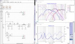
I particularly wanted to get rid of L3, that 2nd large inductor. And maybe reduce the value (and size) of C4 as well. To reiterate, L3 was working to tank the tweeter at its resonance so C4 needed to be reduced anyways in order to increase the roll-off of the tweeter and therefore the level of Fs. I changed my target filters to LR4 at 2300Hz because I now know that to keep the tweeter Fs level well attenuated, a steeper slope is necessary without extra help aimed right at the resonance and going a little higher in frequency won't hurt either in terms of tweeter Fs attenuation as well as trying to minimize that mid suck-out in the midwoofer.
The other 'trick' to help pull down a tweeter Fs is to use a resistor to ground after the rest of the filter, so right before the driver which in combination with R3 the series resistor before the driver forms an L-pad.
The filter values then needed to be tweaked and I went back and forth between a series resistor before the filter and then after the filter on the tweeter before settling on both (plus the resistor to ground).
The results are still not perfect but I think acceptable here for the rears. Impedance and impedance phase have actually been improved.
Larger inductors and capacitors values can get both expensive and big in size whereas resistors are small and cheap, so this xo version has those advantages over the previous one. Perhaps try to get there yourself in your version of XSim. All such efforts are educational. One thing I'm hoping you are starting to see is that there are numerous ways (numerous numerous ways?) to get the job done with the xo. Depends a lot on priorities and then perhaps on which might sound better to your ears.
Attachments
Thank you for the Rears update, because I was thinking the same with the large inductor values how they are for one expensive, but also... large.
So I appreciate the re-do on that! I will try myself tomorrow.
But, for now, I'm going to post what I have done with the towers today. To be clear, I'm not super happy with it. But this is how far I got with the time I had today.
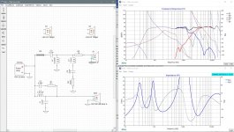
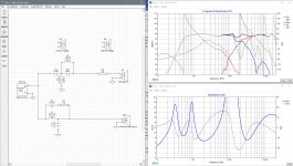
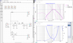
My first two screenshots are just two different approaches that I did for the mid pair. I personally like the second one since it looks more controlled and smooth in the response.
The second screenshoot with the mid and tweeter is pretty good, not super flat, but that would require some crafting to the tweeters FR.
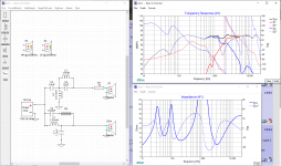
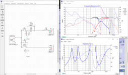
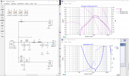
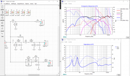
So, then I put in the woofer into the system, since the woofer is a third order the phases for the mid to woofer did not work out (pic 4). So I flipped the mid (Pic 5). I do not know if I should be doing a third order on one driver and then second on the other two, or if I need to keep the orders consistent across all the drivers for phase purposes. Yet, the phases seem to line up pretty well here.
Btw, I can explain more if you want. But in one of my books I found the circuit configuration that is at the start of the woofer signal path. It's called a contour network and is usually used just for full range speakers, but can also be used as a notch filter. I liked it better because it has a wider span to it. I used it to cut down the high end of the woofers cuz there was a wide peak (or mountain) on the woofer high end (~1.5k - 3.5k).
Oh, also C3 is supposed to be an open. I forgot to put it back to that since it didnt do much for what I wanted it to do.
Another area I couldnt control. The valley at 400Hz, just like before with the rears. Dont know what it is, but I'd prefer to not ignore that for the towers. So we will see what we can do.
Last thing and the biggest thing, I could not figure out how to handle the woofer from about 600Hz-2kHz there was a hump that I just couldnt control. Since that makes me have to bring down the mids like a lot in order to get a flat response. Those mids are pretty dang good and I want to use them to their full potential. Wondering your thoughts on that, is it okay to bring the mids down that much and kinda 'bury' them, or not?
Anyways, I hope this doesnt look like a s**t show at least haha. I'll be trying some more things tomorrow.
So I appreciate the re-do on that! I will try myself tomorrow.
But, for now, I'm going to post what I have done with the towers today. To be clear, I'm not super happy with it. But this is how far I got with the time I had today.
My first two screenshots are just two different approaches that I did for the mid pair. I personally like the second one since it looks more controlled and smooth in the response.
The second screenshoot with the mid and tweeter is pretty good, not super flat, but that would require some crafting to the tweeters FR.
So, then I put in the woofer into the system, since the woofer is a third order the phases for the mid to woofer did not work out (pic 4). So I flipped the mid (Pic 5). I do not know if I should be doing a third order on one driver and then second on the other two, or if I need to keep the orders consistent across all the drivers for phase purposes. Yet, the phases seem to line up pretty well here.
Btw, I can explain more if you want. But in one of my books I found the circuit configuration that is at the start of the woofer signal path. It's called a contour network and is usually used just for full range speakers, but can also be used as a notch filter. I liked it better because it has a wider span to it. I used it to cut down the high end of the woofers cuz there was a wide peak (or mountain) on the woofer high end (~1.5k - 3.5k).
Oh, also C3 is supposed to be an open. I forgot to put it back to that since it didnt do much for what I wanted it to do.
Another area I couldnt control. The valley at 400Hz, just like before with the rears. Dont know what it is, but I'd prefer to not ignore that for the towers. So we will see what we can do.
Last thing and the biggest thing, I could not figure out how to handle the woofer from about 600Hz-2kHz there was a hump that I just couldnt control. Since that makes me have to bring down the mids like a lot in order to get a flat response. Those mids are pretty dang good and I want to use them to their full potential. Wondering your thoughts on that, is it okay to bring the mids down that much and kinda 'bury' them, or not?
Anyways, I hope this doesnt look like a s**t show at least haha. I'll be trying some more things tomorrow.
Attachments
It's a little late to give a full analysis but I have to say that's a great 1st effort at a 3-way.
Here's a little more help with your mid target filter: see attached from Response Modeler - I set the xo targets somewhat randomly here just to demonstrate. And I was wrong about the SPL level - it's still set at 90dB but the program sort of reduces it automatically. It's been a while since I went in and did a mid target filter for a 3-way so I got that wrong before because memory failed me. What else is new?
Start again with the woofer though. I suspect that you should be able to simplify that filter, at least to start off with. Think about it - because your xo point is much lower, both your inductor and capacitor values should probably be larger than what you used for the 2-way. You'll also definitely need to bring that mid level down. Nothing wrong with that.
And that's all I've got for tonight. I'll look more closely tomorrow.
Attachments
Let me also add - see it's a little late for me - there are no 'shoulds' for xo orders or driver polarity. There is only what works.
Sounds good and thank you.
I also forgot to say that I was unable to control the impedance, it keeps getting pretty low on some spots. My final one did only have it low at about 10Hz, but Im guessing since the SPL is not much there that it would be fine.
I can do that mid thing on response modeler, but I just did each curve individually. Im guessing thats the same thing.
First a correction from last night - sorry, you rear woofer impedance is 8ohm and your tower woofer impedance is 4ohm so the comparison I made between inductor and capacitor values wasn't valid.
In terms of process, I again start with the woofer, move to the mid and then finish with the tweeter. You may have done it that way but your pics suggest otherwise. Also, driver levels should be at least a little different between the towers and the rears (mic distance and/or pairs vs single drivers) so the amp power may need to be set differently in XSim in order to set your target filters back at the 200Hz woofer level.
Xo targets of 600Hz and 2500Hz seem reasonable based on mid and tweeter center to center spacing, mid 45 degree off-axis response and the dip that the mid has around 3kHz. Maybe looking at whether/where the distortion starts to rise in the LF's of the mids might be worth it too. To get more critical, you could also make sure that there is no problem with xmax for the mids with that xo point and also consider intermodulation distortion for the woofers as the xo frequency goes higher and higher. I've checked out the former in Unibox and it'll be fine and with only 4mm of xmax on the woofers, that's not really a ton of travel to be worrying about its effect on the higher frequencies.
Now here's a little trick to help choose between LR2 and LR4 for the higher xo point: we know the tweeter Fs is at about 800Hz so when you go into Response Modeler to create your target filters, it's very easy to see how far down that frequency is going to be with either LR2 or LR4 at your desired xo points. You should find just like I did with the rears in my last xo version that to keep Fs down about 30dB, you are going to have to go with LR4 at about 2.5kHz instead of LR2 at the same frequency to make that happen. So LR2 may be fine at the woofer/mid xo point but LR4 may be needed at the upper one, which is fine.
Question: are you using the paired measurement for the woofers? Because I can't quite see the null that was created at about 2.3kHz when both were measured together.
Now with the woofers, see if you can't hit your target with just a 2nd order electrical. So I don't think that a contour filter is needed. But you might need a notch filter down quite low due to the interaction of the filter and the woofer impedance peaks. That can be a problem with 3-way woofers depending on a couple of factors and in most cases it needs to be addressed.
Second order on the mid HP and LP sounds about right although sometimes you can get away with just a 1st order HP combined with the natural roll-off of the driver and the addition of a parallel resistor after the filters the way I did with the tweeter in the last version of the rear xo that I posted.
For the necessary roll-off on the tweeter, try going to 3rd order electrical. Copy what I did in that last version of the rears as a starting point if you need to.
And also, depending where they are, don't be afraid of big values. They are necessary sometimes, just try to make sure that the 1st series component is still shouldering as much of the work as possible.
I also forgot to say that I was unable to control the impedance, it keeps getting pretty low on some spots. My final one did only have it low at about 10Hz, but Im guessing since the SPL is not much there that it would be fine.
I can do that mid thing on response modeler, but I just did each curve individually. Im guessing thats the same thing.
You are dealing with 4ohm drivers due to the parallel wiring of driver pairs. So for an amp that can handle 4ohm nominal loads, about 3ohm minimums are acceptable.
Almost the same thing with individual target filters but not quite. By putting them together into 1 target, Response Modeler also automatically adjusts the SPL level that is needed. Plus it simplifies things a little in XSim.
- Home
- Loudspeakers
- Multi-Way
- First-Timer Home Theater Speaker Build