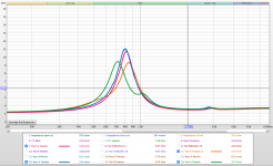
Here is a better look at the tweeter dilemma.
Looking at the screenshot, the most recent tweeter measurements are at the top of the list at the bottom oof the screenshot (7 &12). The tweeter measurements from before are at the very bottom of the list (16 & 18).
Now, I only switched the tweeters that were in Rear A and Tower A. I did not switch any other tweeters. Tweeters also do not rely/change their impedance due to the enclosure. But this clearly shows how different these tweeters are measuring after only taking them out and soldering them in new enclosures. All other measurements are looking good, so my testing setup does not seem to be the one flawed. The only logical thing I can think of that would do such a change is when I solder the wire to the tweeter pins. I read up on it and all I could find is that having too much heat on the tweeter pins could disconnect the little wire in the tweeter and ruin it completely. But it doesnt even to ruin the tweeter, its just changing the impedance responses.
Im at a loss. 🙁
Attachments
So real quick, I have a question about the timing offset in REW.
I have been so far just adjusting the offset time until the distance next to it is equal to the distance from the mic to the driver. But I know there is a "Estimate IR Delay" function which then changes the Timing Offset when going to measure again. Yet when it does that it changes the offset to something that is not the distance from the mic to the driver.
What do you do for that or suggest?
Don't worry about any of the timing setup in REW. You can ignore it because we will be finding the relative acoustic offsets, which is another way of talking about the timing of the different wave fronts, through other means and then we will be extracting our phase information afterwards. So don't worry about that one.
Re the swapped tweeters, it's really hard for me to follow what's happened because both of the rear tweeters were previously labelled the same. I might switch the labelling from location based to actually numbering each of the tweeters. That may reduce any confusion.
If the tweeters are still working, I don't think the soldering is a factor. It certainly does look now like the rear A and Tower A need to be switched. Perhaps you might try working them in a bit prior to measuring and see if that makes any difference. I might also suggest not soldering in the future. Use the appropriate connecting pins instead.
Happy to hear that you found the CC right woofer problem.

Can't say I know what's going on with your Tower woofer tests. Maybe work those drivers in a bit too before measuring. But the averages of several measurements show fantastic similarity so if need be I think it'll be safe to use those.
I understand your frustration though. I'm currently helping my brother out right now with a little project involving some LED strip lighting involving a whole lot of cutting up of the strips and re-wiring them all back together. I've just glued up the 1st two sections (it's an outdoor fountain done in stone tile) with the wiring internalized and somehow 2 of the 4 wires have shorted out. I'm just pulling my hair out right now because I can't find the short and I can't take it apart now either. Maybe there's an easy fix but I sure as heck can't find it right now. 😱
Yeah I wish I labeled the speakers right in my previous screenshot.
But the bottom line was that Rear A and Tower B had the best match. So I put the tweeter in Rear A into Tower A and put the tweeter in Tower A into Rear A. But now, the results look the same. It now looks like Rear A has the better match still, even after I swapped them from before.
....Botton bottom line. After switching tweeters, nothing changed. And that makes no sense to me.
It seem logical to just switch the tweeters again, but I feels like Ill get the same results yet again and go in circles.
I will try and break them in tho.
Also about the woofer tests. I read up on REW Impedance testing and it said to use longer sweeps and also put on the noise filter. After doing those things it looked a lot better!
That sucks to hear about the wiring job shorting out, especially when its installed in stone
Is it for sure a short or an open?
Im down for helpin ya out on that if you would like to give pictures and more details. Up to you!
Wow! So yesterday when I was freaking out about the tweeters, I emailed Parts Express again about if they thought soldering would be creating a problem.
They responded saying that the tweeters I returned back in March were received and tested. They found nothing wrong with the ones we thought were faulty. So weird. So, for good reason, they think my testing setup is wrong.
There must be something in my setup that just doesnt like tweeters for some reason. Such an odd mystery.
So.... I think I would work the tweeters in a little and then measure the impedance again. Than adjust or not adjust given the results and then call it a day. As I say, those small differences down below ~1000Hz are going to be well down in SPL in the xo'd version so don't sweat those differences too much.
Sounds like the woofers are good to go.
Then I would say move on to FR measurements.
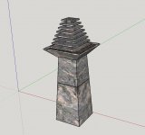
Thanks for the offer of help with my own project but luckily I managed to fix the problem in the last 24 hours. It took me about an hour of section by section continuity testing last night but I thankfully found my problem. I'm layering up 7 pieces of stone on top of each other with center supports in between sort of in a asian pagoda style and doing strip lighting on the perimeters of the undersides of each layer. The connecting wires I'm running up through the center supports. Below is a sketchup rendering of what it's supposed to look like.
So the LED strips I've cut into 4" sections (8" sections for the bigger tiles), glued 4 of them to each of the tiles, connected each section with the necessary 4 wires at right angles and then covered all the connections in silicone. I was super worried that my short was in the connecting wire between the first two layers which I have no chance of getting to after the glue up but thankfully the problem was back in the 2nd to last little 4" lighting strip where 2 of the leads somehow got screwed up.
Easiest thing for me to do was to pull out the first 3 strips on the bottom tile and replace them with new ones. But it was a little easier said than done. There's only an inch and a half in between the tiles so once the layers start going together there is very little room to work with. But thankfully I got it done and now it's on to the next layers. Fingers crossed that was the last and only problem I'm going to encounter. lol. Famous last words.....
Sounds like the woofers are good to go.
Then I would say move on to FR measurements.
Thanks for the offer of help with my own project but luckily I managed to fix the problem in the last 24 hours. It took me about an hour of section by section continuity testing last night but I thankfully found my problem. I'm layering up 7 pieces of stone on top of each other with center supports in between sort of in a asian pagoda style and doing strip lighting on the perimeters of the undersides of each layer. The connecting wires I'm running up through the center supports. Below is a sketchup rendering of what it's supposed to look like.
So the LED strips I've cut into 4" sections (8" sections for the bigger tiles), glued 4 of them to each of the tiles, connected each section with the necessary 4 wires at right angles and then covered all the connections in silicone. I was super worried that my short was in the connecting wire between the first two layers which I have no chance of getting to after the glue up but thankfully the problem was back in the 2nd to last little 4" lighting strip where 2 of the leads somehow got screwed up.
Easiest thing for me to do was to pull out the first 3 strips on the bottom tile and replace them with new ones. But it was a little easier said than done. There's only an inch and a half in between the tiles so once the layers start going together there is very little room to work with. But thankfully I got it done and now it's on to the next layers. Fingers crossed that was the last and only problem I'm going to encounter. lol. Famous last words.....
Attachments
So, question. Thats true that the range of the resonant frequency of these tweeters are going to be so low due to the xo. So, do these differences really matter then? If the different is kinda small and then itll be really tinny when the xo is in there. Why change them around?
Also that tile fountain is so cool! Yeah my only suggestion was to doo continuity tests as well haha. I'm glad you found your problem tho!!
I actually did a project like that in a wine cellar recently. Had to also wire it up custom with LED strips and wire that I braided. Then soldered the connections at the right length and all. Luckily that went pretty smoothly tho!
Yes I mentioned previously that I was a little more interested in any tweeter impedance differences above about 1000Hz and the CC tweeter seemed a bit different than the others so that was best left on its own. But there was such an obvious match or what seemed like an obvious match between 2 of the units that I figured it wouldn't hurt to match those up too. I thought those 2 tweeters matched just a little better way up at the top of the frequency range as well.
But the differences are all very small and I doubt that they'll make much of an audible difference but I guess it's kind of a question of how particular one wants to be. I guess perhaps because I'm trying to teach you the basics, I'm trying not to miss stuff but when the effort exceeds the reward it's usually time to move on.
So I'd say enough with the impedance, on to the FR measurements next.
Yea, the fountain is my brother's project but he's not great with the visualization necessary for design, not so great with tools either and doesn't know anything about electronics so I'm just trying to help him out. I've kind of had to take over the assembly of that top pagoda section because the wiring/soldering has to be done as it's put together layer by layer and well, that's just beyond his skill set at the moment. As long as I don't make any more errors, I should be able to get it back to him in another day or 2. Then I can just return to supervising the rest of the assembly. lol....
And I appreciate you helping me learn this lesson for next time! But yeah there has already been so much effort in the tweeters, it's making the project a chore rather than a joy. I 100% agree it is time to move on! Since the effort is for sure exceeding the reward.
Also to keep in mind. If these were going to be mine, Id do the effort until its OCD right haha. But since it's for my brother, he will not notice any of these small differences at all.
....also if it were mine they wouldnt be white haha
Unfortunately we have some electricians over and they are working right outside the window of the basement with drilling and everything. So, FR will have to wait until tomorrow.
So he doesnt know visualization for design, how to work tools, or electronics. Seems like without you he would have been so so lost haha.
So he doesnt know visualization for design, how to work tools, or electronics. Seems like without you he would have been so so lost haha.
Yes, I think that would be the correct conclusion. 😀
I got all the tiles stacked and glued up last night and this time all the lights are working!! The thing might way about 40 lbs though. I'm scared to try and move the thing.....
Attachments
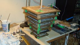
Oh wow that does look intense. Hopefully nothing happens when it gets moved!! 
So, I have just finished all the measurements!
I tried attaching the .zip files but they would never upload. So, I will email you all the .zip files.
Let me know whatcha think!
Ill be looking into how to find the acoustic centers and do the FF and NF combination.
So, I have just finished all the measurements!
I tried attaching the .zip files but they would never upload. So, I will email you all the .zip files.
Let me know whatcha think!
Ill be looking into how to find the acoustic centers and do the FF and NF combination.
Usually Id post a list of questions, but Ill be posting questions here when I have them so I catch you in time haha. Idk if that makes sense, but that's what I'll do right now.
I found that white paper on combining the NF and FF. I also found the links you put in for finding relative acoustic centers.
So, when finding the relative acoustic center, do I need to combined FR of both the woofers and the mids for that? Or will the combined NF and FF for those be used for something else?
Also, in the White Paper, Jeff explains in his example on blending NF and FF that his measurement for FF was on-axis with the woofer. In your list from before there were no on-axis FF measurements for the woofers or mids. Should I do that? Or should I blend the off-axis FF measurement of the woofers with the NF on-axis measurement?
Last edited:
I got your emails and had a chance to look at them this morning but it's the same problem I had before - when I try to open them, REW is not recognizing them as correct files. I'm glad though that you are saving the whole REW file for each batch of measurements. It enables you to come back and re-visit the measurements and manipulate them further if desired/needed. I was worried I forgot to mention that.
For the files, you are going to have to save each individual measurement as frd or zma files and attach those. You are going to need to do this anyways if you haven't already in order to actually work on them. To attach the files here, you do need to change the file extensions to .txt though or maybe you can zip up some of those files and attach that if it's easier or even possible.
Re FF measurements: this harkens back to a discussion we already had and essentially it doesn't make much of a difference if the FF measurements are all on the tweeter axis or if you take FF on-axis with every driver. Neither method is actually using the correct angle of the true FF listening position compared to the FF measurement angles for the mids or woofers but the differences are miniscule and like the problem with your tweeter impedance measurements, those differences will be in frequency ranges that are not within the passband anyways. But the SPL levels for every driver are all correct relative to each other when the mic stays in a fixed position, something that might not be the case if you start moving the mic around for each and every driver.
So no, you don't need to take any more FF measurements. We are going to use the ones you took already for the mids and woofers.
As a next step I suggest working on the relative acoustic center info. Start with the easiest one, the rears and post what you come up with for the woofer delay. If it's looking ok then do it for the rest of the mids and woofers for the other speakers. Tweeter delay is usually considered as the '0' position in XSim btw and the AC's for both identical speakers should be the same too so you just need to do the procedure for 1 of each of the towers and rears.
The procedure in XSim is a little different than in PCD. I think I linked how-to's for both methods but if you have any questions, let me know. The 2 keys are to ensure that you have extracted phase info for drivers and if in doubt, focus on matching responses in the frequencies where both measurements actually overlap.
After that move to the blending process. Again I suggest starting with the simpler 2-ways, posting that and proceeding to the rest if it looks good.
But I'll need your files 1st in order to do the work myself and compare against your's.
So Im going to zip both the .txt and .frd folder for you and email it. Both the same measurements, just different file extensions for you if you need either. DIYaudio's max file size for a .zip is 3.81MB and all these folder, even individually for one speaker, is around 9MB. So it wont work here.
So just to make sure; the blended responses of the woofers and mids are their own thing. They will not be used in finding the acoustic centers. Finding the acoustic centers is purely the use of the FF measurements only.
So just to make sure; the blended responses of the woofers and mids are their own thing. They will not be used in finding the acoustic centers. Finding the acoustic centers is purely the use of the FF measurements only.
OK, files have been received, extracted and successfully imported into REW this time.
Changing the file extension is only necessary when attaching files on this forum. For whatever reason, it's not set up to accept the frd and zma extensions but is fine with txt.
We are going to first use the FF measurements to discover the AC's for the mids and the woofers. That metric is needed to get accuracy in your xo sims. The FF combined driver measurements are used only for this purpose. After that those ones aren't important any more.
But the FF measurements of the single drivers all taken on the tweeter axis are going to be used again in XSim. For the mids and woofers (not necessary for the tweeters) these FF measurements need to be combined with their respective NF measurements before going into the xo program.
The purpose of the off-axis measurements is to help us determine actual xo points for the different drivers and applications. Harmonic distortion measurements are also useful for this purpose and thankfully, every time you have taken a FR measurement in REW, you also have access to the distortion measurements too. That's one reason I'm glad you saved the whole REW measurements sessions.
Good timing btw. I'm pretty much done in terms of the work for my brother which means I can turn my attention back to your speakers now.
I didnt know if XSim needed .txt or not. So I just gave you both.
I'm glad it worked this time tho!!
So, sorry if I feel like a broken record, but I'm still not 100% understanding where and when we use the combined FF and NF.
From you last post it seems like we need the combined responses for later, then we start doing the xo simulations. But for right now, with finding the AC's in XSim, the combined FF and NF responses are not used. Right?
So to put it in a schedule sort of way:
1) Find AC's of the speakers, starting with the rears. The measurements needed for this are just the FF measurements that were taken.
2) Combine the FF and NF responses for the woofers and mids. This combined response will be used when xo sims start.
3) So in the end I should have 5 AC results (one for the rears, two for the towers, and two for the CC). Then, I should have 5 combined FF and NF responses (one for the rear woofers, one for the tower woofers, one for the tower mids, one for the CC woofers, and one for the CC mids).
Does that sound correct?
And sounds great! I'm ready to fully dive into this!
I believe you've got it old chap. 😀
You'll understand more as you go through the process. They're called the relative acoustic centers because not only do they depend on the location of the voice coil and cone on each driver but also because they will vary with where the drivers are placed on the baffle. So x, y and z axes in other words. For this we are using individual and combined FF measurements.
Now for the FR measurements, remember that accuracy is limited depending on the gating. So we do FF measurements with shorter gating for the higher frequencies that includes the baffle effects but not the boundary effects. And we do the NF measurements to get an accurate LF response but that's without the baffle or the boundary effects. So to create the pseudo anechoic measurements for the whole frequency range (well close to the whole range as I'm leaving out the lowest LF's from the ports) we have to combine the FF and the NF measurements, being sure to also include the simulated baffle effects to the NF measurements before combining and being careful of the frequency range within which we choose to combine them.
See if that's starting to make sense yet.
Great! 😀
So I did the FF and NF blending already since I've done that before, haha oops didnt follow my so called schedule.
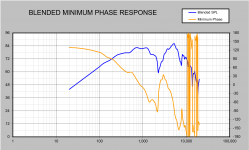
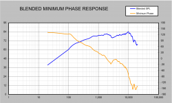
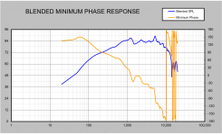
I have some screenshots of the results. I also have the FRD files of the results. I did include the simulated baffle effects into the NF for each. I also blended in the range given which was 200Hz - 500Hz. Was a few where I would blend up to 550Hz. But that range actually seemed like a good spot for all of them.
So screenshots are in this order:
Tower A Woofer Blended
Tower A Mids Blended
Rear B Woofer Blended
CC Right Woofer Blended
CC Mids Blended
I also did this for Tower B and Rear A, as well as the left woofer in the CC. I'm only attaching the 5 types of blended here.
So I did the FF and NF blending already since I've done that before, haha oops didnt follow my so called schedule.
I have some screenshots of the results. I also have the FRD files of the results. I did include the simulated baffle effects into the NF for each. I also blended in the range given which was 200Hz - 500Hz. Was a few where I would blend up to 550Hz. But that range actually seemed like a good spot for all of them.
So screenshots are in this order:
Tower A Woofer Blended
Tower A Mids Blended
Rear B Woofer Blended
CC Right Woofer Blended
CC Mids Blended
I also did this for Tower B and Rear A, as well as the left woofer in the CC. I'm only attaching the 5 types of blended here.
Attachments


Oh also while I just read article on finding the AC in XSim, I got a question.
In the article it states, "However, since the microphone is placed on axis with the midrange driver, the sound coming from the mid arrives first, in our case. You want to leave the delay of the front most speaker set to 0 (zero)."
Which makes sense! And you did tell me that since the mic was on-axis to the tweeter that the delay for that should be zero.
But! In my speakers design the tweeter is flush mounted while the mids are then tucked a little bit on top of tweeters face. So, if you were to look at the speaker in a side view, the mids are further out than the tweeter.
I know that the mids are slightly off-axis to the mic since it was pointed at the tweeter. But, what do you think about that?
Should I still have my tweeter just set to a delay of zero?
Also, in that link, Speaker Acoustic Center, it says, "Next step is to load the combined response file so it shows on our graph... Green line – Is the measured response of all the speakers wired in parallel." But I did not take any measurements of all the drivers tied in parallel. But I did do the measurements of all the pairs. So what do you suggest for that?
Should I blend the Tweeter+Mids FRD with the Mids+Woofers FRD together somewhere in the midrange? So that way I get the full-band combined response of all the drivers?
Last edited:
Well I haven't had the chance yet to start working on the FR combining but my first glance at your attachments is telling me that something doesn't look right.
I remember way back in high school math, I had a teacher who told me always look at your answer in the end and see if it makes sense and I think that's good advice for speaker design too. So take a look at Dayton's RS 150P-8's FR from its spec sheet. Flat to 200Hz and almost to 100hz as well. Now total baffle step loss is 6dB at the lowest frequencies so you should expect that to be the absolute maximum SPL loss in your combined FR result down near 100Hz and even just a little less than that up at 200Hz.
But what does your 1st graph show? If you kind of ignore the mid peak and consider the woofer level to be at about 78db, the response is down more than 12dB at 100Hz and about 6dB at 200Hz. That's not what's to be expected from the effects of baffle step loss. So something is off in other words. I'm going to have to go through it myself 1st to be able to give you more insight into that though.
For the AC, you are kind of getting ahead of yourself. The point of the exercise is to determine exactly what the offset is empirically. Set your on-axis driver (in your case the tweeters) to 0 and then match up the curves to determine the other offsets. If the AC for 1 of the drivers is more forward than the tweeter, then you'll get a negative result from XSim. If the AC is behind the tweeter's, then you'll get a positive result.
One thing I don't like about that instructional that you linked to is exactly the point you are hitting on - wiring up 3 drivers together in parallel and taking that combined FR. Why? Because as you start to wire up more and more drivers in parallel without any xo's to separate the signal, the impedance load you are presenting to your amplifier gets lower and lower. That might be ok with 3 x 8ohm loads and a good amp, but with 4ohm loads - it's not something I'm going to comfortably recommend. Which is why I had you take the measurements in a series of pairs instead and also why I wanted you to begin with just a single pair in the 2-way to start with. Then once you had that successfully under your belt and understood, then I would have explained how to extrapolate that to your 3-ways.
So to wit, let's start with your 2-way - finding the relative acoustic center of the woofer:
1. open XSim and wire up 2 drivers in parallel and a 3rd driver just unattached to anything
2. import the rear tweeter FF FR and choose derived as your FRD phase source (you'll be asked to 'tail' the ends of the FR, the low end isn't going to matter for the tweeter and set the top end similar to the slope that exists prior to it, in this case -24dB/octave above 20kHz)
3. import the rear woofer FF FR and derive phase again. Choose something like about 50Hz and -4.5dB/octave for the low end and the same -24dB/octave at 20kHz for the top end.
4. import the rear FF combined tweeter and woofer measurement into the 3rd driver. Ignore phase for this one.
5. Now in the FR chart turn the phase off for the system response and turn on the "(curve only)" for the 3rd driver, the tweeter and woofer combined response (choose a different color than the system response).
6. Now open up the woofer again and start increasing the delay until the 2 curves match. When they do, you're done. That's the appropriate delay for the rear woofer when the tweeter delay is set to 0.
Give that a try. See what you get and see if you can also understand what you're doing and why it works. Try to just do that and only that and get back to me.
I need to take a closer look at your measurements next which I haven't had the chance to do yet. Ok, just a very quick look right now and my 1st question is why are your NF measurements stopping at 100Hz? The NF are meant to measure the LF response which should include below 100Hz. Have you gated these or did you just start them that high?
Thank you for that reminder, it's only been a year and a half out of college but wow how can I forget something as elementary as that haha. Much appreciated!
But that is very true and something does seem to be off. I do admit since I was already gating at 4-5ms for all the other measurements I did forget to lower the start frequency for the NF responses. I'll do that hopefully today or tomorrow. So, cant I just take a NF of one of each? Since the NF doesn't incorporate the baffle effects, I can use a NF response of a woofer on the rears for combination of the woofers on the towers, correct?
Also yeah I guess I did not get why you wanted me to do the rears first, my bad. Ill do that now and get back to you with my observations on that.
- Home
- Loudspeakers
- Multi-Way
- First-Timer Home Theater Speaker Build