Re CC mid chamber size - for HT, 1 of the most important things is dialog intelligibility. Or in other words, your CC. So in that respect getting the mids right in the CC is actually more important than in the L&R.
And in my experience, the impression of a speaker's size is determined by its front baffle dimensions. Adding depth is often not noticed.
Again, the extra volume and insulation and back wave absorption is a small improvement not a deal breaker. But they can add up. Again, your choice.
+1 and as my avatar kind of implies, my audio background is rooted in [home] cinema, so believe anyone even remotely serious about it needs at least a 'bare bones' background in it to drive 'home' 😉 just how important and how to go about it: http://education.lenardaudio.com/en/17_cinema.htm
Right, we can use horn polar response theory to 'close enough' predict how much:
Horn mouth polar frequency:
c = 10^6/[a*b]
a = wall angle in deg
b = mouth width in inches
c = frequency
For example; a 24" wide x 12" high baffle will normally have a 90 deg angle in both planes, so loads down to ~463 Hz x ~926 Hz, averaging out to ~[463*926]^0.5 = ~655 Hz.
From this we see that it's much too small to add any BSC, but big enough to potentially put ~an octave's worth of mids 'bump' in the response right where we normally least want it ['honk']: Interactive Frequency Chart from Independent Recording Network – Alexey Khlystov – My creativity on the one page
Depth of course holds to the same rules and why some folks marvel at the seeming conundrum of really narrow [HF width], though 'deep', towers supporting low bass.
GM
Doesn't the baffle have a loss? A loss could simply be equalised correct again and it would sound the same.And in my experience, the impression of a speaker's size is determined by its front baffle dimensions.
I don't think we are talking about the same things Allen.
I'm referring to aesthetics. To the visual impression of a big speaker. So if 1 speaker is say, 8" x 20" x 10" (WxHxD) and a 2nd speaker is 8" x 20" x 14", they aren't going to seem that much different. On the other hand, a 12" x 30" x 4" speaker will definitely seem larger than the 8" x 20" x 10" speaker even though the former is smaller in the depth dimension and the latter is actually larger in the internal volume dimension.
I'm referring to aesthetics. To the visual impression of a big speaker. So if 1 speaker is say, 8" x 20" x 10" (WxHxD) and a 2nd speaker is 8" x 20" x 14", they aren't going to seem that much different. On the other hand, a 12" x 30" x 4" speaker will definitely seem larger than the 8" x 20" x 10" speaker even though the former is smaller in the depth dimension and the latter is actually larger in the internal volume dimension.
Okay so I am just gunna lay everything out on the table because I want to share the progress from today.
Here is a list of something I have gathered first:
- my brother will no use the rears as monitors, so a tuning of 71Hz will be fine for the design
- my brother has ensured that he will make sure all speakers will be away from the wall and to leave the port in the back of the speakers
- I have decided to do slot ports for the CC and my brother likes the look of them
So, I have also put Dayton's specs into Unibox as well and been messing around with that. The changes are not too drastically different in the results. With that in mind, I have followed Parts Express suggestion for a vented volume of 7.65L @ 71Hz for the RS150P. So, for the rears and the CC I am going to be going with that. I also checked with Unibox and that checks out.
I know you have been suggesting larger volumes which still would work out. But, due to the design desire to have the speakers smaller, I have been going with the 7.65L.
The slot is 1" wide and 6.75" tall, so in area that equals to a 2.932" round port, and that is what I put into Unibox. Then since my slot if 1" wide, the port end correction is 0.5, which I now just noticed that would be in cm....
In my design below I have the port equal to 12.06" from Unibox. But now with my unit error, it should be 9.05". So that will change.
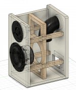
Been working a lot on this to get all my variable in place. The good news is now all the speakers are tuned below 80Hz. Though I am wondering your opinion on the CC design. Since the rear didnt change volume wise, I only moved the woofer down and countersinked it.
I am not countersinking the mids in the CC because that would sacrifice more height to the CC, which I already raised it 0.25" to accommodate for the chamfer not being under the bottom of the box. Now there is a good amount of room for the mids from the walls imo.
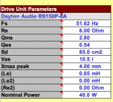
I have also included the screen shot of my measured for the RS150P T/S parameters below.
Here is a list of something I have gathered first:
- my brother will no use the rears as monitors, so a tuning of 71Hz will be fine for the design
- my brother has ensured that he will make sure all speakers will be away from the wall and to leave the port in the back of the speakers
- I have decided to do slot ports for the CC and my brother likes the look of them
So, I have also put Dayton's specs into Unibox as well and been messing around with that. The changes are not too drastically different in the results. With that in mind, I have followed Parts Express suggestion for a vented volume of 7.65L @ 71Hz for the RS150P. So, for the rears and the CC I am going to be going with that. I also checked with Unibox and that checks out.
I know you have been suggesting larger volumes which still would work out. But, due to the design desire to have the speakers smaller, I have been going with the 7.65L.
The slot is 1" wide and 6.75" tall, so in area that equals to a 2.932" round port, and that is what I put into Unibox. Then since my slot if 1" wide, the port end correction is 0.5, which I now just noticed that would be in cm....
In my design below I have the port equal to 12.06" from Unibox. But now with my unit error, it should be 9.05". So that will change.
Been working a lot on this to get all my variable in place. The good news is now all the speakers are tuned below 80Hz. Though I am wondering your opinion on the CC design. Since the rear didnt change volume wise, I only moved the woofer down and countersinked it.
I am not countersinking the mids in the CC because that would sacrifice more height to the CC, which I already raised it 0.25" to accommodate for the chamfer not being under the bottom of the box. Now there is a good amount of room for the mids from the walls imo.
I have also included the screen shot of my measured for the RS150P T/S parameters below.
Give me a little time to work over the details. I may have a few suggestions to make but overall it looks good. The consultation with your brother is excellent btw. I think getting his input into the speakers will make him happier with them in the end.
Might be a good time for me to ask what type of wood you are going to be using.
Might be a good time for me to ask what type of wood you are going to be using.
Right then, a few things to take note of, in no particular order.
- The cross sectional area of the port can be smaller. A 2" diameter port is fine for each individual driver. So an area of 3.14 sq inches. That'll mean they can be shorter too.
- Just in the interests of smaller sizing, the slot port wood needn't be 3/4" thick. Half inch or even 1/4" will do the job. Unless, you wanted to make parts of the slot ports double up as some kind of side panel bracing.......mmmmh
- For the port tuning for the CC (and for the rears too I think), I would suggest keeping it low enough so that the LF peaking not exceed 2dB when using your measured parameters (0dB or 1dB is fine too). So something like 7.65L with Fb=60Hz and a port 2"x5.5" results in a 2dB peak at 85Hz. But you can get something similar with a slightly smaller Vb I think if you want to again keep it smaller.
- It looks like the mids' overlap of the tweeter faceplate is going to occur right over the tweeter faceplate's screw holes. The holes are recessed but make sure you can get a low profile screw head that will be as flush as possible.
- If you do a 45 degree chamfer behind the mid cutouts, it looks to me like the bottom panel will be above the lowest part of the chamfer. Not a big deal if you also recess the bottom panel into the front one. Or sit the whole front baffle on top of the bottom panel instead of the bottom panel butted up against the front one. If that's not clear see below. Can't say I've routed in this type of situation before but it may make a difference in the order that you do the work - ie. route the chamfers 1st on a bigger piece of wood and then run it through the table saw and cut the panel to the right height dimensions afterward. I'm just not sure about the router bit as it moves into that bottom open little area and tear out.
- Two of the woofer chamber dimensions are pretty much the same, 8.69" and 8.5". This means you have 2 possible standing waves at about the same frequency. Best to make all 3 dimensions a little bit more different if you can.
- In the sims I've done, I'm finding it difficult to get the mid lower xo point down around 300-400Hz which is where I thought it might be best. Instead I can't get much below 600Hz before the impedance starts dropping too low. Which means that again if you want to make things a little smaller, the mid chamber size can be reduced by a liter or 2 since it won't be seeing frequencies as low as I thought it might (but the reduction should include any bracing and damping I suggest below). Maybe put an angle to the side separators if you want.
- Subpanel dimensions are pretty close to the same for the mid and woofer chambers this time (close to 9"x 9") which means all of them are going to have primary resonances in the about same ballpark - probably about 900-1200Hz for 3/4" MDF. That works fine for the woofer chamber this time as those'll be operating under 600Hz but it's not so good for the mids. This time we have to employ a different strategy because we can't push the resonance either above or below the mids' passband. So in this case, it's best to brace it, damp it and insulate it. One vertical brace from front to back will split the panels up again and should send the resonance up above 2000Hz where it's a little easier for the insulation to absorb the energy and where there is a little less energy in music to start off with too. I would consider a smaller, like 3/4"x 2", horizontal brace across the middle too to maybe stiffen the vertical brace. I'd consider running those right through the woofer chambers to the 2 side panels too but you'll have to get creative to get around the slot ports.
- Lastly, my xo sims are showing that you are going to need some somewhat large capacitor values on the woofer filter. For these you are going to want to use the less expensive nonpolarized electrolytic caps. Much, much cheaper and smaller too. The one drawback however is that they have a limited lifespan, maybe 20-25 years. So if you think these might last this long, it'd be a good idea to make sure access to those xo filters is possible. If you don't want to go with a removable back just make sure you plan to put them in a place that is serviceable from a front driver hole that you can get your hand through. So probably behind a woofer. And perhaps on a separate small board that can fit through the hole too.
Attachments
Two of the woofer chamber dimensions are pretty much the same, 8.69" and 8.5". This means you have 2 possible standing waves at about the same frequency. Best to make all 3 dimensions a little bit more different if you can.
Maybe you figured this one out - standard convention says to keep the panel dimensions all different but here in this application as a woofer chamber in a 3-way that will only see frequencies below about 600Hz, the chamber will never actually see the frequencies for standing waves at those dimensions, ie. ~1700Hz. So please ignore my comment above. A cube with all 3 dimensions equal to 8" or 9" would be fine here. I needed an extra day to remember to actually look at the specific frequencies involved.
On another note, you may have a bit of a problem with level matching with your tweeters. Maybe, maybe not. It's hard for me to say at this point but I wanted to mention it anyways.
Sensitivity for the DC28FT is just barely making it up to the level of the rest of the drivers. See below for a first go at the CC xo. As it is, the summed response has just a slight downward tilt which should work out fine, but it's just a simulation - if for any reason you want to adjust the tweeter level upwards a touch in the real world, you aren't going to be able to do so because it's already running full out.
Now the spec sheet for the DC28F-8 shows the same response as the DC28FT-8 but the DC28FS-8 shows something different and yet it's supposed to be the same tweeter but with magnetic shielding. SPL level is actually up around 94dB and yet the sensitivity listed for the tweeter is the same as the others - 89dB at 1W/1m. So I'm not sure about the accuracy there. I've got an email into Dayton this morning to see if they can shed any light on the matter. If the graphed FR is correct, then you have plenty of leeway to play with. But if the FR is more like the other 28F versions, then you have the same potential problem with all your tweeters.
Like I said, I'm not sure if it'll be a problem or not. But normally I like to have a little flexibility to play with in terms of level matching driver SPL's. Anyways, just really wanted to let you know.
Attachments
Thank you, I am trying to include my brother in all the conversations and details going on to get his input, and of course make him happy with the results.
I’ve talked to my brother and he says that he would want a good plywood for the speakers. I was thinking like a really good grade baltic-birch ply or something.
I have a couple reasons I have the slot port that equals to a 3” round port:
- I wanted the slot to be as tall as the CC cabinet so that no extra wood for a shorter slot would be needed and I made it 1” wide so that its not too narrow where you can possibly hear the “tube-ness” of the slot port.
- Also, a larger port diameter yields a larger length, which I wanted cuz the 2” diameter came out to be like 7” long. But I have read everywhere that the back of a port should not be atleast 3” away from the adjacent panel. I do not know if that constraint also applies to slot port, but I am assuming it does. So, I wanted the slot port long enough to get the angle on it, so that the end of the slot is more than 3” away from the adjacent cabinet wall.
Also, yes I used 3/4” wood for the slot port because it would also act as bracing for the woofer chambers, and that way I do not need to buy extra 1/2” wood. I can just use scraps of the 3/4” wood Ill already have.
So how low do you suggest I get the CC and rears so that the LF peaking does not exceed over 80Hz? Also, how did you check for that so I can look into that as well.
That is a good point @jReave, the mids will be right over the tweeters screws. Now, the tweeter faceplate does not have recessed screw holes, I will just get a countersink bit and make some, then get screws to fit flush. Since the faceplate is only plastic, we can adjust it for the needs.
When I raised the height of the CC by 1/4” it also raised the bottom of the mid chamfers above the top of the bottom panel. There might be a very very small amount that might hit the bottom panel. But when I am making the box, I will make sure to not route too far on the chamfers to ensure it will not be a problem.
Okay, I will look into the bracing for the mid chamber today and volume changes with the angle pieces. I will send that later today.
So, why do you suggest that I would want to go with the smaller and less expensive caps? I think if my brother is willing to go for the more expensive caps, then is there any other constraint about a larger cap?
But, I am thinking about making the back panel removable for future services, so I will also be looking into that today.
In terms of the sensitivity of the tweeters. If the overall FR of the drivers are not completely flat, cant we put some resistors on the mids and woofers to slightly pull them down to make the overall FR flat. This would slightly reduce the over max SPL, but if it leads to a smooth FR I think that would be ideal.
But some possible inaccuracy with Dayton! Makes me wanna trust my measured T/S parameters now haha.
About the bracing, because I am a little confused.
You said that the woofer chambers are good without the bracing due to the resonance being above the xo point. But then you said to put bracing from the mid chamber to the woofers chambers? I just dont know if that is necessary, since that will also mean I will need to make up some lost volume from the braces.
Also, for the bracing of the mid chamber. The vertical brace, do you suggest a brace the ones we have been doing with the full size and the holes. Or, do you suggest like a 2" x 2" x 6.75" brace vertically in the middle of the mid chamber? Or even a 2" dowel rod in the middle. Or maybe a small version of this https://www.diyaudio.com/forums/attachments/multi-way/734552d1549535299-designing-speaker-scratch-images-thread-woofer-box-brace-2_0-jpg
Good Baltic Birch is generally considered better material than MDF because it’s stiffer and so panel resonances will be higher than with MDF. Some say its damping properties are better too but I haven't seen the data to confirm that. The extra stiffness is better for braces too. Do note that the 1 place that that is undesirable in your designs is with the mid chambers in the L&R speakers where we were trying to keep the panel resonances below the mid passband, ie. below ~500Hz. We may need to change the bracing strategy for those so it’s the same as for the mid chambers in the CC.
The rule of thumb that I know for port clearance for a round port is a distance equal to the port diameter. Maybe it’s slightly different for slot ports but I don’t think so. The 1 negative about your longer port is that air flow is not as smooth in a right angle change of direction. Still, many people use them that way, sometimes with multiple right angle changes. In terms of wood usage, if you use 1 piece of wood that is 6.75” tall for the 3 sq in port or 3 pieces of wood that are 1” x 3.14” x 1” for the 2 sq in port, the latter actually uses less wood. Also avoiding a too narrow slot port is a sound strategy. Here I'm just trying to provide information. The choice is up to you.
Re port peaking, this may be a little confusing because we are dealing with 2 sets of TS parameters - like a first time designer needs things to be even more complicated than they usually are – I don’t think so! 😱 Regardless, you want to avoid any excessive peaking in the vented alignment. But you don’t know which T/S parameters are right. So you want to make sure that if you choose a particular Vb and port size, then no matter which set of parameters are correct, you will end up with a LF peak that is less than 2 dB.
How do you do that? Lowering your tuning frequency will reduce the peaking. So will lowering the box volume. Or a combination of both. So just as an eg., try 7L tuned to 65Hz with a 5x14.6cm port using Dayton’s data. You should get a 1 dB peak at 96Hz. Then try with your measured data. Keep it at 7L but this time change the port tuning until the port length equals about 14.6cm. If your measured data are correct, this will therefore be the response in the same box and port, this time with about a .5dB peak at 105Hz. It doesn’t matter that the F3 is below 80Hz. That’s just the minimum you ideally want to get down to. You can just as easily cross to the sub at 60Hz or maybe 70Hz depending on the particular AVR.
The woofer filter is going to need 2 large caps, both of them in parallel lines going to ground, also called shunts. One is likely to be about 100uF and the other anywhere between 200uF and 400uF. Take a moment and search PE for the price and the size of putting these values together using film and foil or polypropylene capacitors. Ouch. Ouch. Ouch. Seriously. Generally, you need the better components in series with the drivers and you can get away with less expensive versions in the shunts. And I also have a philosophy of keeping the price and quality of xo components consistent with the price and quality of the drivers. The Dayton drivers are very good, particularly good in value but they don’t warrant extravagant xo component purchases imho.
Dayton did actually get back to me today to let me know that the graph and frd file for the DC28FS-8 is actually incorrect. So most likely it is also only about 90dB in sensitivity. But the good news is that the FR is much more likely to be the same as the CC tweeter. So better front soundstage matching. Dropping the woofer level with resistance may indeed be a possibility but it is universally considered a no-no. The bulk of the power is going into the woofers so to throw resistance in front of it is just a waste. It may be a better idea to just let the AVR’s internal eq system handle the discrepancy although I don’t like to rely on that. For me personally when I listen to music, I set my AVR to pure direct which bypasses all the internal processing but therefore relies on the front L&R speakers to be tuned properly to begin with. I don’t really know what to say about this - either buy all new tweeters now with higher sensitivity or just wait until you have measured the drivers in-cabinet and we'll can see what we can do.
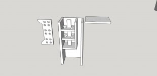
I can understand the confusion about the mid bracing. I’m trying to keep my posts short but you can see how well that is working out and still my explanations can fall short. If we are trying to go with a stiff bracing strategy, then the stiffness of the actual bracing matters. Not only do we want to prevent the panels from flexing, but we want to prevent the bracing from flexing too. So a cross brace through the mid center brace is intended to stiffen the mid center brace and the extension of that cross bracing into the woofer chambers is intended to continue that horizontal stiffness. But that’s probably a bit of overkill so I think you can probably forego that suggestion. If you want. Pics are below but they are definitely not to scale. Just intended to give you a visualization of what I was thinking. Note on 1 side I've got the 3 sq in port and on the other I've got something like a 2 sq in port.
The rule of thumb that I know for port clearance for a round port is a distance equal to the port diameter. Maybe it’s slightly different for slot ports but I don’t think so. The 1 negative about your longer port is that air flow is not as smooth in a right angle change of direction. Still, many people use them that way, sometimes with multiple right angle changes. In terms of wood usage, if you use 1 piece of wood that is 6.75” tall for the 3 sq in port or 3 pieces of wood that are 1” x 3.14” x 1” for the 2 sq in port, the latter actually uses less wood. Also avoiding a too narrow slot port is a sound strategy. Here I'm just trying to provide information. The choice is up to you.
Re port peaking, this may be a little confusing because we are dealing with 2 sets of TS parameters - like a first time designer needs things to be even more complicated than they usually are – I don’t think so! 😱 Regardless, you want to avoid any excessive peaking in the vented alignment. But you don’t know which T/S parameters are right. So you want to make sure that if you choose a particular Vb and port size, then no matter which set of parameters are correct, you will end up with a LF peak that is less than 2 dB.
How do you do that? Lowering your tuning frequency will reduce the peaking. So will lowering the box volume. Or a combination of both. So just as an eg., try 7L tuned to 65Hz with a 5x14.6cm port using Dayton’s data. You should get a 1 dB peak at 96Hz. Then try with your measured data. Keep it at 7L but this time change the port tuning until the port length equals about 14.6cm. If your measured data are correct, this will therefore be the response in the same box and port, this time with about a .5dB peak at 105Hz. It doesn’t matter that the F3 is below 80Hz. That’s just the minimum you ideally want to get down to. You can just as easily cross to the sub at 60Hz or maybe 70Hz depending on the particular AVR.
The woofer filter is going to need 2 large caps, both of them in parallel lines going to ground, also called shunts. One is likely to be about 100uF and the other anywhere between 200uF and 400uF. Take a moment and search PE for the price and the size of putting these values together using film and foil or polypropylene capacitors. Ouch. Ouch. Ouch. Seriously. Generally, you need the better components in series with the drivers and you can get away with less expensive versions in the shunts. And I also have a philosophy of keeping the price and quality of xo components consistent with the price and quality of the drivers. The Dayton drivers are very good, particularly good in value but they don’t warrant extravagant xo component purchases imho.
Dayton did actually get back to me today to let me know that the graph and frd file for the DC28FS-8 is actually incorrect. So most likely it is also only about 90dB in sensitivity. But the good news is that the FR is much more likely to be the same as the CC tweeter. So better front soundstage matching. Dropping the woofer level with resistance may indeed be a possibility but it is universally considered a no-no. The bulk of the power is going into the woofers so to throw resistance in front of it is just a waste. It may be a better idea to just let the AVR’s internal eq system handle the discrepancy although I don’t like to rely on that. For me personally when I listen to music, I set my AVR to pure direct which bypasses all the internal processing but therefore relies on the front L&R speakers to be tuned properly to begin with. I don’t really know what to say about this - either buy all new tweeters now with higher sensitivity or just wait until you have measured the drivers in-cabinet and we'll can see what we can do.
I can understand the confusion about the mid bracing. I’m trying to keep my posts short but you can see how well that is working out and still my explanations can fall short. If we are trying to go with a stiff bracing strategy, then the stiffness of the actual bracing matters. Not only do we want to prevent the panels from flexing, but we want to prevent the bracing from flexing too. So a cross brace through the mid center brace is intended to stiffen the mid center brace and the extension of that cross bracing into the woofer chambers is intended to continue that horizontal stiffness. But that’s probably a bit of overkill so I think you can probably forego that suggestion. If you want. Pics are below but they are definitely not to scale. Just intended to give you a visualization of what I was thinking. Note on 1 side I've got the 3 sq in port and on the other I've got something like a 2 sq in port.
Attachments

Alright I got some good stuff for ya today. *Fingers crossed* it's all good haha
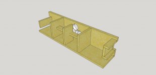
Okay, so I have went with a tuning of 60Hz for both the CC and the surrounds, but have 2" diameter ports.
Firstly, the panel resonances in the mid-chamber with the towers does make sense how it needs to be higher than the bandpass now with a stiffer wood. So the first screenshot is a new brace I put into the mid-chamber of the towers.
Secondly, I have worked on the bracing of the surrounds. [Screenshot 2] and attached PDF.
I went with the technique that I attached in my last post. I have a circle in the vertical brace that is the diameter of the back of the RS150P, so that the brace is not directly behind the woofer. Not sure that matters, but thats why there is one circle in the vertical brace. Due to the lower tuning, I need the port to be an elbow down. I did not 3D model that very well, but the port in my drawings is basically what I will be doing. I will most likely be going with a PVC elbow and tubes for the surround ports.
The rears came out to be a net volume of 7.62L @ 60Hz, with a 2" diameter port that is 5.75" long.
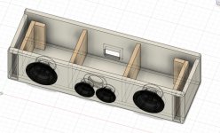
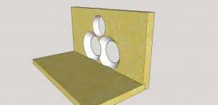
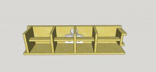
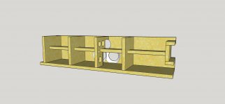
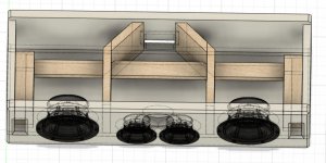
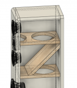
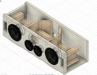
Lastly, I have also worked on the center channel in changing the slot port, the tuning, the bracing, and trying to make the mid chamber not too "boxy". [Screenshot 3, 4, and 5] and attached PDF.
So, I have taken your advice in the horizontal brace across the CC. It wasnt clear, but it seemed like you wanted one long piece of wood that goes thru the entire length of the CC. But I just did three individual pieces to not make anymore room for leaks.
Also, now the slot port is 1" x 3.14". It does make sense how the air would not be as smooth in a right angle port, so yeah the slot is now smaller and shorter.
For the woofer chambers, the net volume is 7.18L @ 60Hz, with a 1" x 3.14" slot port that is 6.311". In Unibox, for the given volume of tuning, it tells me I need a port of 6.24". But I figured to have the brace at the end of the port and also at the bend of mid chamber walls, so I figured a slightly longer port will only make the tuning slightly lower, so why not.
For the mid chamber, the net volume is 6.76L.
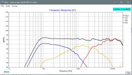
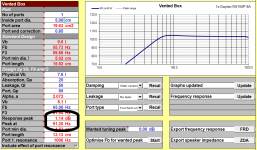
I was looking into the peaking and was noticing that I am getting a change of ~3dB from the tuning frequency of 60Hz to about 80Hz, yet from 80Hz on the difference was under .5dB
So, I guess I am still confused on that haha sorry. To me, there is no significant (over 2dB0 peak past 80Hz, and that would still work for the design. The speakers can still then be crossed over at 80Hz.
Wow yeah, that its true how dang expensive those larger caps are. But how much longer is their life from the regular caps? Like, if they last a life time, wouldnt it be worth it to just get those to not have to get the speaker serviced over so many years? so, the conversation of keep the quality of xo components consistent with the quality of the drivers seem like a fair point. But idk it seems like a topic of debate, only out of curiosity really. But! since I start building the boxes next, week I am going to save that for later haha.
Again, wow, that is surprising how Dayton supplied incorrect files and data. Did they say anything about sending you an updated version of all that?
I like to keep the tweeters I have now, but what about the Dayton Audio RST28F-4 1-1/8"? They have a sensitivity of 93.5dB @ 2.83V/1m.
But, welp, I just looked and I ordered the tweeters on August 20th, so today is literally the 60 day mark in order to return the drivers thru Parts Express.
Anyways, I hope the designs are good in your eyes! Let me know about anything you see that night need to change, or if they are good to go!
Okay, so I have went with a tuning of 60Hz for both the CC and the surrounds, but have 2" diameter ports.
Firstly, the panel resonances in the mid-chamber with the towers does make sense how it needs to be higher than the bandpass now with a stiffer wood. So the first screenshot is a new brace I put into the mid-chamber of the towers.
Secondly, I have worked on the bracing of the surrounds. [Screenshot 2] and attached PDF.
I went with the technique that I attached in my last post. I have a circle in the vertical brace that is the diameter of the back of the RS150P, so that the brace is not directly behind the woofer. Not sure that matters, but thats why there is one circle in the vertical brace. Due to the lower tuning, I need the port to be an elbow down. I did not 3D model that very well, but the port in my drawings is basically what I will be doing. I will most likely be going with a PVC elbow and tubes for the surround ports.
The rears came out to be a net volume of 7.62L @ 60Hz, with a 2" diameter port that is 5.75" long.
Lastly, I have also worked on the center channel in changing the slot port, the tuning, the bracing, and trying to make the mid chamber not too "boxy". [Screenshot 3, 4, and 5] and attached PDF.
So, I have taken your advice in the horizontal brace across the CC. It wasnt clear, but it seemed like you wanted one long piece of wood that goes thru the entire length of the CC. But I just did three individual pieces to not make anymore room for leaks.
Also, now the slot port is 1" x 3.14". It does make sense how the air would not be as smooth in a right angle port, so yeah the slot is now smaller and shorter.
For the woofer chambers, the net volume is 7.18L @ 60Hz, with a 1" x 3.14" slot port that is 6.311". In Unibox, for the given volume of tuning, it tells me I need a port of 6.24". But I figured to have the brace at the end of the port and also at the bend of mid chamber walls, so I figured a slightly longer port will only make the tuning slightly lower, so why not.
For the mid chamber, the net volume is 6.76L.
I was looking into the peaking and was noticing that I am getting a change of ~3dB from the tuning frequency of 60Hz to about 80Hz, yet from 80Hz on the difference was under .5dB
So, I guess I am still confused on that haha sorry. To me, there is no significant (over 2dB0 peak past 80Hz, and that would still work for the design. The speakers can still then be crossed over at 80Hz.
Wow yeah, that its true how dang expensive those larger caps are. But how much longer is their life from the regular caps? Like, if they last a life time, wouldnt it be worth it to just get those to not have to get the speaker serviced over so many years? so, the conversation of keep the quality of xo components consistent with the quality of the drivers seem like a fair point. But idk it seems like a topic of debate, only out of curiosity really. But! since I start building the boxes next, week I am going to save that for later haha.
Again, wow, that is surprising how Dayton supplied incorrect files and data. Did they say anything about sending you an updated version of all that?
I like to keep the tweeters I have now, but what about the Dayton Audio RST28F-4 1-1/8"? They have a sensitivity of 93.5dB @ 2.83V/1m.
But, welp, I just looked and I ordered the tweeters on August 20th, so today is literally the 60 day mark in order to return the drivers thru Parts Express.
Anyways, I hope the designs are good in your eyes! Let me know about anything you see that night need to change, or if they are good to go!
Attachments
-
Center Assembly Drawing v4.pdf242.1 KB · Views: 78
-
Rear Assembly Drawing v2.pdf173.6 KB · Views: 125
-
 Screen Shot 2020-10-20 at 3.14.41 PM.jpg135.2 KB · Views: 72
 -
 Screen Shot 2020-10-20 at 3.14.01 PM.jpg132.8 KB · Views: 83
 -
 Screen Shot 2020-10-20 at 11.52.38 AM.png883.5 KB · Views: 131
 -
 Screen Shot 2020-10-20 at 12.27.07 PM.jpg141.9 KB · Views: 115
 -
 Screen Shot 2020-10-20 at 3.13.36 PM.jpg231.2 KB · Views: 88
I won't have time until tomorrow to go over things but I would get on the phone with Dayton asap and tell them you bought all the tweeters based on the faulty spec sheet and with the knowledge right now that the sensitivity is going to be questionable for your design, I think they will probably accept taking them back. Dayton actually has a very good reputation for customer service.
The RS28 tweeters look great. It's a flatter FR and I think the quality is better too. And there is a truncated faceplate as well. Ordering those as replacements should clinch the deal on the return, I would think.
The RS28 tweeters look great. It's a flatter FR and I think the quality is better too. And there is a truncated faceplate as well. Ordering those as replacements should clinch the deal on the return, I would think.
Can you forward the email to me. And show that it was sent from Dayton Audio, Parts Express needs it to verify the fault.
Or post a screen shot of the email.
Or post a screen shot of the email.
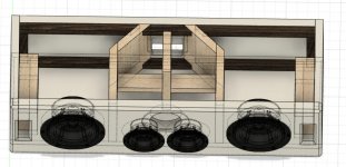
Box tuning looks good. I think anything from 7-7.6L with a 2” x 5” or 6” port is going to work fine with the RS150P. When I was talking about the peaking, Unibox is kind enough to list that along with where it’s happening. See pic 1 below. For the woofer tuning in the towers, tune them as low as they’ll go while maintaining a flat response. So no peaking this time.
Back to the towers. I think you should make the mid chamber design a little more straight forward and with a little more bracing now. By that I mean just a simple rectangular box with a matrix style of bracing that you posted a pic of earlier. About 6” of depth looks good. That’ll be 6.5” x 13.75” x 6” for 8.8L net. So the strategy is to brace, damp and insulate now when the resonances are likely to still be in the driver’s passband.
For the side panels (13.75”x6”) the resonance is likely to fall between 1200Hz and 1700Hz. If you split the panel roughly in half horizontally, the resonances are likely to be between 2100Hz and 2800Hz. That’s actually pretty good. But if you go with 2 horizontal braces, the resonances should end up about 3000Hz to 4000Hz. That’s all for good quality Baltic birch based on the panel resonance formula I linked to previously. Because I don’t have enough empirical data to validate the accuracy of that formula in real world cabinets and because panel resonance behavior is more complex than a simple formula anyways, I would err on the overkill side unless there are some other mitigating design parameters.
Next, the top panel will be 6.5”x 6”, so a resonance between about 2100Hz and 2800Hz so again we might want to throw a brace at that and perhaps at the same time use that brace to stiffen the horizontal braces. So that’s a vertical brace from top to bottom running through the middle (ie. the weakest place) of the horizontal braces. (I think 1 piece of wood with insets that will slip together with horizontal braces is better but gluing in 3 smaller pieces for each section will work too.) Because you want to keep the cabs small, I think you can just use a smaller piece of wood here (like ¾” x 2”) instead of running that brace from front to back. A rough pic is below. To the left is something like what a larger front to back (almost) vertical brace might look like if you cared to go bigger. I’m being conservative with how much wood I cut out and making sure there is always solid wood at the critical mid points, side to side, front to back and top to bottom.
Next I’d line the side, top and back walls and probably the back of the front baffle too with ¼” of damping material, typically bitumen sheets but there are other diy methods to choose from too to damp the walls. For me, I’d probably go to about ½” or even use a ½” or ¾” of constrained layer damping. These additions will reduce the net volume which is 1 of the reasons to start off with the larger chamber.
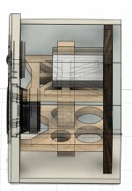
Hopefully that might inform the bracing for the other speakers too. I like the changes to the CC but the bracing still isn’t quite right. The panel that will be the most problematic in terms of audibility will be the mid top panel but – no bracing there. Do a vertical brace there and then the horizontal braces are there to stiffen that one. Another rough pic attached below. Again, extending that horizontal bracing through the woofer chambers is probably overkill and so skippable (is that a word?).
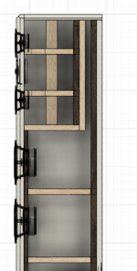
Now the rears - I prefer all braces to be oriented from back to front. This allows the maximum freedom of energy movement from the driver to the back of the speaker. A window type brace whose face is parallel to the front and back panels is not doing this which is how you’ve got it. It potentially presents more surface area to the rear waves so that the sound can be reflected back to the driver, though that depends on frequency, panel size and box dimensions. And given that orientation and with the location of where the large circular cutout sits, there is no way to stiffen the brace at the critical center locations either. Also, the very thin horizontal side bracing you have pictured I don’t think are stiff enough to be doing much of anything. Unfortunately.
Looking at resonances again, the side panels are 8.13” x 11.875” which will give a primary resonance between about 850Hz to 1200Hz. With 1 horizontal brace, you are looking at about 2000Hz to 2700Hz for the subpanels. With 2 horizontal braces, 3000Hz to 3700Hz. So just like the mid chamber in the towers, I’d go with the 2 horizontal braces with 1 vertical brace to keep them stiff and increase the resonances of the top and bottom panels as well. Another pic below.
The problem with the vertical brace in the rear speaker of course is that the port will get in the way. There are maybe a couple of creative ways to get around that but I think the simplest and easiest is to go with slot ports again. Two rectangular ones up in the top back corners should work again but so too would 2 triangular ones which is what I have pictured. Well I put 1 of them into the drawing only because I got lazy. The other would go on the other side. I think my sizing was 1.8" x 1.8" and a length of ~6". I used a single piece of 1/4" wood to make it happen.
And about window braces. My pics show 3 different ways to cut out material from them. From worst to best, I’ve got rectangular cutouts, circular cutouts (arches are stronger than rectangles) and triangular cutouts in what I call a starburst pattern (triangles are stronger than arches – I think). Notice also that the starburst pattern interconnects everything to the 4 stiffest places of a cabinet – the 4 corners. (If the middle of the panels are the places that are going to be moving the most, the corners are the places that are going to be moving the least.) Pick what suits your fancy or perhaps is easier to build.
One more thing to mention with multiple horizontal braces. It can actually be a good thing to vary the pattern of cutouts so that you don't leave clear pathways from top to bottom which will make standing waves easier to form.
Left up to you is to decide on the details of the bracing and then recalculate net volume and make any necessary adjustments.
Another long post but hopefully that might provide the last info you need to finalize the designs.
Back to the towers. I think you should make the mid chamber design a little more straight forward and with a little more bracing now. By that I mean just a simple rectangular box with a matrix style of bracing that you posted a pic of earlier. About 6” of depth looks good. That’ll be 6.5” x 13.75” x 6” for 8.8L net. So the strategy is to brace, damp and insulate now when the resonances are likely to still be in the driver’s passband.
For the side panels (13.75”x6”) the resonance is likely to fall between 1200Hz and 1700Hz. If you split the panel roughly in half horizontally, the resonances are likely to be between 2100Hz and 2800Hz. That’s actually pretty good. But if you go with 2 horizontal braces, the resonances should end up about 3000Hz to 4000Hz. That’s all for good quality Baltic birch based on the panel resonance formula I linked to previously. Because I don’t have enough empirical data to validate the accuracy of that formula in real world cabinets and because panel resonance behavior is more complex than a simple formula anyways, I would err on the overkill side unless there are some other mitigating design parameters.
Next, the top panel will be 6.5”x 6”, so a resonance between about 2100Hz and 2800Hz so again we might want to throw a brace at that and perhaps at the same time use that brace to stiffen the horizontal braces. So that’s a vertical brace from top to bottom running through the middle (ie. the weakest place) of the horizontal braces. (I think 1 piece of wood with insets that will slip together with horizontal braces is better but gluing in 3 smaller pieces for each section will work too.) Because you want to keep the cabs small, I think you can just use a smaller piece of wood here (like ¾” x 2”) instead of running that brace from front to back. A rough pic is below. To the left is something like what a larger front to back (almost) vertical brace might look like if you cared to go bigger. I’m being conservative with how much wood I cut out and making sure there is always solid wood at the critical mid points, side to side, front to back and top to bottom.
Next I’d line the side, top and back walls and probably the back of the front baffle too with ¼” of damping material, typically bitumen sheets but there are other diy methods to choose from too to damp the walls. For me, I’d probably go to about ½” or even use a ½” or ¾” of constrained layer damping. These additions will reduce the net volume which is 1 of the reasons to start off with the larger chamber.
Hopefully that might inform the bracing for the other speakers too. I like the changes to the CC but the bracing still isn’t quite right. The panel that will be the most problematic in terms of audibility will be the mid top panel but – no bracing there. Do a vertical brace there and then the horizontal braces are there to stiffen that one. Another rough pic attached below. Again, extending that horizontal bracing through the woofer chambers is probably overkill and so skippable (is that a word?).
Now the rears - I prefer all braces to be oriented from back to front. This allows the maximum freedom of energy movement from the driver to the back of the speaker. A window type brace whose face is parallel to the front and back panels is not doing this which is how you’ve got it. It potentially presents more surface area to the rear waves so that the sound can be reflected back to the driver, though that depends on frequency, panel size and box dimensions. And given that orientation and with the location of where the large circular cutout sits, there is no way to stiffen the brace at the critical center locations either. Also, the very thin horizontal side bracing you have pictured I don’t think are stiff enough to be doing much of anything. Unfortunately.
Looking at resonances again, the side panels are 8.13” x 11.875” which will give a primary resonance between about 850Hz to 1200Hz. With 1 horizontal brace, you are looking at about 2000Hz to 2700Hz for the subpanels. With 2 horizontal braces, 3000Hz to 3700Hz. So just like the mid chamber in the towers, I’d go with the 2 horizontal braces with 1 vertical brace to keep them stiff and increase the resonances of the top and bottom panels as well. Another pic below.
The problem with the vertical brace in the rear speaker of course is that the port will get in the way. There are maybe a couple of creative ways to get around that but I think the simplest and easiest is to go with slot ports again. Two rectangular ones up in the top back corners should work again but so too would 2 triangular ones which is what I have pictured. Well I put 1 of them into the drawing only because I got lazy. The other would go on the other side. I think my sizing was 1.8" x 1.8" and a length of ~6". I used a single piece of 1/4" wood to make it happen.
And about window braces. My pics show 3 different ways to cut out material from them. From worst to best, I’ve got rectangular cutouts, circular cutouts (arches are stronger than rectangles) and triangular cutouts in what I call a starburst pattern (triangles are stronger than arches – I think). Notice also that the starburst pattern interconnects everything to the 4 stiffest places of a cabinet – the 4 corners. (If the middle of the panels are the places that are going to be moving the most, the corners are the places that are going to be moving the least.) Pick what suits your fancy or perhaps is easier to build.
One more thing to mention with multiple horizontal braces. It can actually be a good thing to vary the pattern of cutouts so that you don't leave clear pathways from top to bottom which will make standing waves easier to form.
Left up to you is to decide on the details of the bracing and then recalculate net volume and make any necessary adjustments.
Another long post but hopefully that might provide the last info you need to finalize the designs.
Attachments

Last edited:
This did really help and made a lot of sense. Thank you.
So here I have screen captures of the updated designs with the bracing. As well as updated to show 0.75" x 075" strips on the back so that the back can be removed. I will also be putting a foam gasket on the back of those strips so that the back is screwed on air tight.
The net volume of the woofer chamber in the CC and the towers are still the same as before.
I have not figured out the net volume of the mid-chamber in the towers or the CC yet, been working on trying to get some wood and finish the CAD designs. Nor have I found the exact net volume of the rears, but I will make sure that it turns out to be ~7.2L.
Both the CC and rears are still tuned to 60Hz.
Sorry I do not have much time for a detailed post, though let me know about anything you need from me. But I have also looked into the peaking and I'm only getting about +1.8dB around 94Hz. Kinda like your screenshot, so the peaking is under control now.
Also, I cannot find a plywood sheet of 1" baltic birch for all the front baffles. Yet, my grandfather has a high-grade sheet of 1" maple he thinks. Im going to do research on it to see if maple will be okay as front baffles. Wondering your thoughts.
Thank you!
Attachments

Fantastic. 🙂
That all looks pretty good now. It's a little difficult for me to see what you are doing for the port in the rears so I'll just wait for the next drawing.
For the towers, do take a moment to ensure that if you remove the back panel to the mid chamber, that there is enough clearance to pull it out through the opening on the back of the whole cabinet. Might be pretty hard if both back panels are the same width. Or because you are going with a removable back panel now, it might be easier to just add in those couple of extra inches and make the mid chamber the whole depth of the cabinet.
Hope you had success with your tweeters.
- Home
- Loudspeakers
- Multi-Way
- First-Timer Home Theater Speaker Build