Aavid Thermalloy 4180G, these ALUMINUM OXIDE insulators looks so expensive, but they are actually under 1,- EUR/USD !
I received your email Lazy Cat, to all others following, the FO 1.4M is in stock.
I received your email Lazy Cat, to all others following, the FO 1.4M is in stock.
Did-you mean... each ?Aavid Thermalloy 4180G, these ALUMINUM OXIDE insulators looks so expensive, but they are actually under 1,- EUR/USD !
What do-you expect ? Some 1/10 of PF between tracks on the printed circuit and ground ?Alumina spacers look fantastic. Can't wait to hear it.
I eat my hat if it makes the slightest différence that we could measure. May-be one or two degres on the thermal side ?
This said, I whould prefer (on the thermal side) if manufacturers could provide their heat sinks with a hard anodized isolated mounting face. In the mass.
Same remark about the CPUs of our computers: We all fight with massive cooling systems, while most of the losses in thermal conductivity is between the die of the CPU itself... and their external mounting face.
Esperado,
I know this is very off topic here but are you saying you would want the heat sink on your computer CPU to be anodized on the mounting surface, black I assume? Wouldn't that anodizing actually be an insulator at that interface? I can see on the radiation surface but on the interface I'm having trouble following the logic of that.
I know this is very off topic here but are you saying you would want the heat sink on your computer CPU to be anodized on the mounting surface, black I assume? Wouldn't that anodizing actually be an insulator at that interface? I can see on the radiation surface but on the interface I'm having trouble following the logic of that.
it is probably because i was not clear enough.I'm having trouble following the logic of that.
While some are polishing the mirror surface of their heat sink in their computers, or use of a supposed better thermal past, Intel, as an example, don't seen to try their best to optimize the thermal resistance between the die of their processors and their external surface in contact with the coolers.
So, you can fight as much as you can to keep your heat sink at <30°, fighting to gain a degree, in the same time the CPU will measure its internal temperature at >80° at full load.
Last edited:
Thanks Christophe,
Yes not much you can do about what Intel does inside the CPU. Glad we still have AMD to make them stay on their toes.
Yes not much you can do about what Intel does inside the CPU. Glad we still have AMD to make them stay on their toes.
Oh, by the way, I am often surprised by the little diameters of the cables most of you are using in your builds for your wires from PSU to Amp's rails and speaker's to amps outputs.
I'm sure there is more to gain on the quality of the transients and overall dynamic here than using expensive ceramic insulators.
I'm sure there is more to gain on the quality of the transients and overall dynamic here than using expensive ceramic insulators.
Last edited:
Oh, by the way, I am often surprised by the little diameters of the cables most of you are using in your builds for your wires from PSU to Amp's rails and speaker's to amps outputs.
I am often surprised by the thin wires inside IGBT transistors. And the cary 50, 100 and more amps.
What is you concern?
You want to compare a distance about 2 mm inside an IGBT with a long thin cable 15 or 20 cm?I am often surprised by the thin wires inside IGBT transistors. And the cary 50, 100 and more amps.
What is you concern?
You want to compare a distance about 2 mm inside an IGBT with a long thin cable 15 or 20 cm?
All we need to compare is resistance of the cable being used. If the resistance is too high it will influence the frequency response of the bass and overall speaker behaviour.
I prefer thin cables that push skin effect outside of audibility.
So short, imagine their resistances, and cooled by their two extremities ?I am often surprised by the thin wires inside IGBT transistors. And the cary 50, 100 and more amps.
What is you concern?
So short, imagine their resistances ... and cooled by their two extremities ?I am often surprised by the thin wires inside IGBT transistors. And the cary 50, 100 and more amps.
What is you concern?
1- Suspected skin effects at the frequencies we are talking about? Do-we try to balance the HF impedance of our speaker's cables ?I prefer thin cables that push skin effect outside of audibility.
2- About "skin effects", figure out why we use big diameters single strand wires in radio emitters and even cables from satellites parabolas ?
Kin effects for electrons are like speedways for you: You prefer the right lane when you are alone, but you take an other free one when there is too many cars in the right lane: they will find the easiest way for them, don't worry ;-)
On my side, After a lot of purely subjective tests, I tend to prefer (when possible) single strand wires, and, when I am obliged to use more than one for flexibility, parallel ones isolated from each others. I Use CAT 5 for low or medium power signal connections.
Just a personal taste, nothing "scientific".
I believe we are polluting LC's thread with this OT that always menace to be never ending.
Everyone has their preferences and it is hard to convince other's unless they try different options...that said, I believe that it is equally (if not most) important the material of the cables themselves and especially the material of the speaker binding post.
I prefer OCC copper (mono-crystal) by far (interconnect; power; speaker) and I do not use speaker binding posts, safe for applying the force needed for the cables to make proper contact. 😎
The other option is directly soldering the speaker cable to the amp module, but, while feasible, it is risky... 😱
Cheers,
M.
Hi guys 
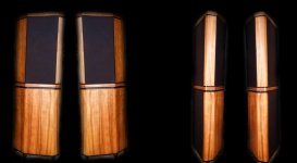
Just to inform you that the first batch of First One modules went out to travel the world, also one upgrade of a ready made First One dual-mono amplifier went to Sweden.
Also few tests were performed in recent week:
- ESP Monitor + Bassoon, First One clearly over performed MC² Audio T1000 power amp on Basson module, unbelievably but deeper more controlled bass with FO
- First One bi-amping of B&W 802-D3 with Anagram DAC source blow our minds
- my soul's favourite ALTEC Lansing Model Fourteen shows how good speakers were in eighties, match made in heaven, SONY's TA-N80ES didn't stand a chance
L.C.
Attachments


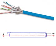
As I said, for line, I use exclusively Network STP CAT5-6 cables. Not expensive, very common, four mono strand twisted pairs individually shielded with a shield around them. You can use them with symmetric and asymmetric connections as well.Esperado what cable do you suggest or prefer for line and speaker?
For asymetric links, I use to cable them as on the attached image.
In my active system, I use them as well between my active fitter and my enclosures: One pair for Basses channel, one pair for treebles channel, one pair for power on command (+12V), one pair for mute signal (+12V).
For Speakers, As all my speakers are compensated to present a flat impedance curve, cables does not matter so much: I use as big diameter and less expensive copper cables that i can, following the advice of Peter Walker (QUAD founder), who answered this cable's question that way: "I tend to prefer the ones that conduct electricity."
Attachments
Last edited:
Heatsinks and the rest of the chassis were not grounded even before, only RF decoupling, otherwise complete galvanic isolation from chassis to module.
So, the manual that came with the 1.2 was wrong in this respect, or is there an updated manual?
So, the manual that came with the 1.2 was wrong in this respect, or is there an updated manual?
All First One v1.4 M modules equipped with brand new instructions. 😉
Attachments
- Home
- Vendor's Bazaar
- First One - mosFET amplifier module