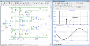
If you follow the first path that Kyrill Hammer called (do not use negative feedback), then you can make such an amplifier of an economical class A (quiescent current 1 A). The output stage is a pseudo-two-cycle Taylor follower. At full power, distortions at a frequency of 20 kHz do not exceed 0.05%, and starting from the first period (FCD)
Attachments
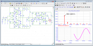
At full power, distortions at a frequency of 20 kHz do not exceed 0.05%, and starting from the first period (FCD)
If distortions are 0.05% then it's still not full power.
Wow, that was a useful post... 😕
Do you know what Mark means by non-stationary distortion?
Yes: "an audible distortion that doesn't stay constant long enough to show up well in a relatively longer distortion measurement time frame"
I agree, in clipping mode at THD = 10%, the output power is fullerIf distortions are 0.05% then it's still not full power.
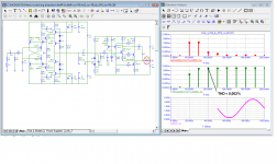
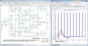
Here is a variant of the amplifier developed by Hiraga and modified under the conditions of Jiri Dostal and Cyrill Hammer. Due to the high frequency of the first pole, the phase of the Loop Gain in the sound band is zero, so there is no increase in higher harmonics, the spectrum is like in the best tube amplifiers.
Attachments
I agree, in clipping mode at THD = 10%, the output power is fuller
Usualy THD=1% is considered the threshold where full power is reached.
a question to the fighter for the correct models.petr, don't bother trying to powder it up to make it look good in a hurry. Once I have found why your simulation did not give you an oscillator, I don't mind it being stable or not anymore. And, "the coordination of cascades", that shows you know too little about the people in this forum for you to "lecture" to, is not a fix to the poor transistor models.
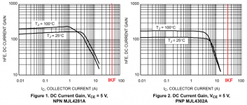
How much should the IKF value be in the correct models of these transistors?
Attachments
You still don't get it do you? What a waste of all those explanations of the knowledgeable people here! What's the expression, pearls before swines?
Jan
Jan
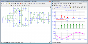
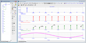
Still not clear? You do not pass the signal through any circuit that limits the frequency range from above. Of course, 2*2=4, why are you surprised? What did you expect to see something different?😀For skeptics of first-cycle distortion
9 harmonics added to 1 kHz signal at 30 V peak in the spectrum of the first period, we observe all harmonics with a level of 1% and total THD = 3%
... and nothing new!
You still don't get it do you? What a waste of all those explanations of the knowledgeable people here! What's the expression, pearls before swines?
Jan
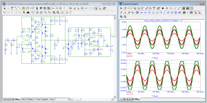
I mixed harmonics into the main useful signal, and we see them in the spectrum of the first period. If you remove them, then the spectrum will be clean. Similarly, in the spectrum at the amplifier output, what the amplifier introduces is what we see. This is what Graham tried unsuccessfully to prove. Jean, you're right, it's useless to scatter beads in front of pigs
I mixed harmonics into the main useful signal, and we see them in the spectrum of the first period. If you remove them, then the spectrum will be clean.
Of course! Did you expect otherwise??
And of course the spectrum will be clean when you remove them. Please Google 'synchronous FFT'. That is when you do when you FFT the input 1st cycle. In that case, the initial step function does not enter the picture.
Similarly, in the spectrum at the amplifier output, what the amplifier introduces is what we see. This is what Graham tried unsuccessfully to prove.
What is there to proof??
Can you take some time to explain to us what exactly is your point, because you keep on going from one point to another.
Jan
- Home
- Amplifiers
- Solid State
- First cycle distortion - Graham, what is that?