What was the difference?I can hear the difference. The differences are significant. Not like a fraction of a percent of THD. You can hear it.
That is a more difficult question. In summary, clarity of the music improves with a clean supply, so I can hear individual instruments and voices/vocals better.What was the difference?
No click on turnon. The Cap Multiplier has an inherent slow turnon. The rail voltage at the output rises slowly as a function of the filter RC constant.
No noise from the speakers at idle. There was not much even with the conventional supply, but you could hear a bit from a foot or so from the speaker. Normally, one tends to dismiss it if you can't hear it a few feet away, but if the cause is power supply noise, then it will get bigger with load later when playing, and it will affect the sound.
In fact this is what I noticed, especially at medium-to-moderately loud levels. A noisy supply causes some loss in detail and clarity. VSSA is an exceptionally clear and crisp sounding amplifier, and you can tell.
No noise visible on the output with my oscilloscope. With a conventional power supply, you can see some evidence of switching noise when you set the trigger to "Line" (mains frequency). With the Cap Multiplier filter, no noise down to 10 millivolts.
Bass passages are cleaner with the Cap multiplier PSU. Probably, because the bass load does not modulate the rails (or not as much). The Cap Multiplier effectively pushes the rail drop caused by the greater bass load into the subsonic range. Other filtered supplies can do this too, it is not unique in this regard, but it is cool to see this on the scope, and then hear the difference.
What was the difference?
I am using professional studio monitor loudspeakers (Tannoy K2558) with horn loaded HF driver. Recently I built P3A amp and tried it with both conventional PSU (bridge rectifier + cap bank) and with MrEvil's cap multiplier. With conventional PSU you can hear broadband HF noise when you put your ear close to HF driver. With cap multiplier - nothing!
I also tried conventional PSU with simple VSSA circuit (one without CCS). Hum/buzz was so loud that you can hear it from 2 meters distance. With cap multiplier - nothing! This particular circuit must use very low noise PSU like MrEvil's cap multiplier.
Conclusion: cap multiplier is always beneficial.
hi Ranchu32,
I don't see many disadvantages, but it brings additional complexity and it has no intrinsic short circuit protection on output, so the input fuses are mandatory. they may save the day when properly calibrated.
i wonder if a fall-back short circuit protection can be implemented, as it is not uncommon to see power MOSFETS go short-circuit when fail.
On the other hand, even without cap multiplier, a short circuit of the rails to Ground may also lead to huge disaster when unfused.
Cheers!
I designed PS regulator(actually capacitance multiplier similar to this one) with all needed protection included, over current protection, DC on the amp output, high transient surge at the amp input.
It saved ones my speaker when oone channel of of my amp crashed and showed high DC at the output.
I used it in my TT amp here, look file PS-regulator-BJT-b-sch http://www.diyaudio.com/forums/solid-state/182554-thermaltrak-tmc-amp-10.html#post3031504
It is in use for more then a year with no problem, apsolute noise free and pop free.
@metallicus: When you say "input fuses" are you referring to the fuses which are installed between the reservoir caps and the pass transistor? Or fuses at the amplifier boards, or something else?hi Ranchu32,
I don't see many disadvantages, but it brings additional complexity and it has no intrinsic short circuit protection on output, so the input fuses are mandatory. they may save the day when properly calibrated.
i wonder if a fall-back short circuit protection can be implemented, as it is not uncommon to see power MOSFETS go short-circuit when fail.
On the other hand, even without cap multiplier, a short circuit of the rails to Ground may also lead to huge disaster when unfused.
Cheers!
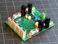
I tested the fuses on the power supply board, and they definitely work as protection against shorts and over-current (tested), without damage to the pass transistors or any other fireworks. If I missed something here, please post what it is, b/c I am in the process of sending out a few dozen of these boards to other people. If there is a potential issue with the fuses, I am sure they would like to know... 😀
Attachments
Like most linear regulators, it relies on the voltage drop across the pass transistor to work correctly. So with a conventional transistor, or a typical Darlington-type circuit, the efficiency can be low, and it can force you into selecting a transformer with higher secondary voltage. What I like about this circuit, is that the voltage drop (Vdrop) can be as low as 0.5V, and still provide great results. So basically, you can just put it in place of a conventional supply, with no impact on the overall design.Pardon my ignorance, but what are the disadvantages of a cap multiplier?
High Voltages: You have to select components with correct ratings. Up to +/-50V rails, that is not an issue, but above 50V it takes some effort, at least for people who can't order from Mouser or Farnell without excessive shipping costs. (I am working on that, but not there yet). There is not going to be a single best answer, like below 50V.
High Currents: Coupled with higher required Vdrop, the power dissipated in the pass transistor must be managed more carefully. I tried to design the board with this in mind (you can mount the transistors from below and on a bigger heatsink), but that does require more work, and not a practical solution for everyone.
The only disadvantages I can see are:
more cost
more space
more voltage drop (= less power)
more risk of unreliability.
I would certainly advise a cap multiplier, rather than voltage regulator for a power amplifier.
more cost
more space
more voltage drop (= less power)
more risk of unreliability.
I would certainly advise a cap multiplier, rather than voltage regulator for a power amplifier.
I made the assumption that fewer large aluminum electrolytic caps would be used, which means that the cost and space would be same or smaller.The only disadvantages I can see are:
more cost
more space
more voltage drop (= less power)
more risk of unreliability.
I would certainly advise a cap multiplier, rather than voltage regulator for a power amplifier.
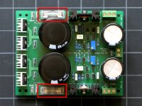
The pic below shows the first version of the Cap Multiplier pcb (on the right), next to a board with three pairs of 4700uFd caps (middle). With three pairs of 10.000uFd capacitors, the boards would be about the same size.
The 10.000uFd Panasonic caps I bought recently at Mouser were about $12~13/pair. By coincidence, the cost of all the semiconductors and other small parts is about equivalent to the cost of two additional large caps, somewhere between $10 and $15, depending on where you source them from.
For my purposes, I would have had to use three (maybe four) pairs of 10.000 uFd caps, with series resistors, to get close to the same result. When I tried, traces of the diode switching noise were still present. I have no idea how many uFd it would take to get the noise down to 10~20mV, and with Mr Evil's circuit, I am there or below.
@AndrewT: I am having a hard time measuring the inrush/chassis fuse current. I do not have a true Peak-Reading multimeter. Triggering my old scope to measure with a shunt has proven to be difficult, and the only CT I have at my disposal is huge (useless at small currents). I have ordered a better one with more sensitivity, but it will take 1-2 weeks.
Open to suggestions, if you have one, but for now I have reached the limit of what I can do with the stuff on hand... 🙁
Attachments

@metallicus: When you say "input fuses" are you referring to the fuses which are installed between the reservoir caps and the pass transistor? Or fuses at the amplifier boards, or something else?/QUOTE]
Hi Pete,
Yes, I was refering to those fuses between big caps and pass transistor. I didn't test yet this cap multiplier so I was not sure a short at the output will end up in smoke or will break the fuses. Do you use fast fuses? Anyway, it's nice to hear that pass transistors can stand short term abuse! 🙂
Cheers!
After a few days of using cap multiplier with P3A amp I re-connected ordinary PSU. The difference in SQ is obvious. The sound is much better with cap multiplier. The retrieval of fine detail, speed and resolution is much better with cap multiplier. I must admit that I am somewhat surprised because P3A has decent PSRR but obviously even amps with decent PSRR could greatly benefit from use of such PSU. With ordinary supply P3A sounds like good quality industrially mass produced amp, with cap multiplier it reaches the level of audiophile class.
Yes, fast blow only. I am not sure that the pass transistor would survive with a slow-blow fuse...😀...
Yes, I was refering to those fuses between big caps and pass transistor. I didn't test yet this cap multiplier so I was not sure a short at the output will end up in smoke or will break the fuses. Do you use fast fuses? Anyway, it's nice to hear that pass transistors can stand short term abuse! 🙂
PMI,
What us the result on the cap multiplier if you use larger caps than the 4700uFd values you have on the right hand board. Let us suppose you substituted 10000uFD in their place? Is there any difference or is that academic at that point?
What us the result on the cap multiplier if you use larger caps than the 4700uFd values you have on the right hand board. Let us suppose you substituted 10000uFD in their place? Is there any difference or is that academic at that point?
I used the largest cap I thought would make some sense for a 100W/channel amplifier. There is something to be gained by substituting a cap with lower ESR (at much higher cost), but larger value, not so much.PMI,
What us the result on the cap multiplier if you use larger caps than the 4700uFd values you have on the right hand board. Let us suppose you substituted 10000uFD in their place? Is there any difference or is that academic at that point?
VSSA (which is what I am using to test) has large-ish low ESR bypass caps on board, so at mid-to-high audio range, most of the energy comes from there. At low-mid range and Bass, the pass transistor with its low on-resistance is close to transparent, so the input and output caps basically act together, as if they were in parallel. You could improve this a bit by using the pair of transistors that Metallicus posted above, those have even lower on-resistance (tradeoff, higher cost). It will only make a difference at higher power though, their rating is around 100A... welding current! 😱
Overall the transient response is much better than my previous favorite C-L-C-R-C setup. Very close to my bench supply, which is bigger than the whole amp even with fans inside.
On the front side, I plan to experiment with larger-value/lower voltage reservoir caps (before the cap multiplier filter), to get closer to an ideal combination for Class A amps. This will result in proportionally smaller ripple, smaller required Vdrop, and therefore less heat to get rid off.
Thanks PMI,
All of the things I had been reading up to now were with unregulated power supplies using the c-r-c-r-c type of topology so I am new to this cap multiplier design. Most of the amplifier circuits I am looking at are as you say no more than 100watts@8ohms so this looks like the right approach for that.
All of the things I had been reading up to now were with unregulated power supplies using the c-r-c-r-c type of topology so I am new to this cap multiplier design. Most of the amplifier circuits I am looking at are as you say no more than 100watts@8ohms so this looks like the right approach for that.
PMI, on a slightly unrelated topic...
I'm building a simple linear power supply for a DX MkIII amplifier and your first photo I found interesting. I was planning to take the 16 capacitors and glue them to a sheet of perspex and then use strips of copper sheet to connect the pins. Your implementation below using stripboard seems much easier. Can you give me some more details? I'm wondering whether the copper cladding on the stripboard is thick enough for high current?

I'm building a simple linear power supply for a DX MkIII amplifier and your first photo I found interesting. I was planning to take the 16 capacitors and glue them to a sheet of perspex and then use strips of copper sheet to connect the pins. Your implementation below using stripboard seems much easier. Can you give me some more details? I'm wondering whether the copper cladding on the stripboard is thick enough for high current?
The copper on standard strip board is narrow.
You should look at paralleling 3 or 4 strips for low impedance.
By paralleling you can bring the strips for +ve and 0 and -ve closer together to reduce the loop area.
I prefer to hardwire. This allows close coupling of the wiring and even twisting on EVERY connection.
You should look at paralleling 3 or 4 strips for low impedance.
By paralleling you can bring the strips for +ve and 0 and -ve closer together to reduce the loop area.
I prefer to hardwire. This allows close coupling of the wiring and even twisting on EVERY connection.
I suppose that depends on the plating of the board, but in any case these boards just have evenly spaced holes, and the connections are soldered solid copper and tinned copper wire on the bottom side. I used those when I was doing some comparison noise and ripple tests. (Just never had time to post it all) They make it easier to attach smaller parts, but I don't think it makes any difference for the main caps. On the left in the picture, the extra parts were removed, so you only see the large caps. The one in the middle is a small CLCRC, with some additional small caps and other stuff under the board....I'm wondering whether the copper cladding on the stripboard is thick enough for high current?
If you want a large capacitor bank to lower the mains ripple and to have a lot of reserve energy in the supply, then almost anything will do just fine (and what you are planning may be better).
There is another thread where Gootee gives a method to calculate the capacitor value needed in excel tor a particular ripple value where an alternative method is proposed to mount the capacitors, The capacitors are mounted to a two sided copper clad board and this was shown to be superior to a point to point wiring layout. I think it was a way to decrease the L values to the lowest value between the capacitors. Look for Gootee's posts.
- Status
- Not open for further replies.
- Home
- Amplifiers
- Power Supplies
- Finished capacitance multiplier