No, this test was not intended to show that. I do not have equipment that could show an accurate input signal reading and an output measurement at one time, in one screen shot.Does this mean that VSSA needs 3V input for max output? If so, that's very low input sensitivity, isn't it?
Off topic, but for what it's worth:
This set of boards was actually modified to be close to LC's modules, so I could test this, but I could not show it in one screen pic. Even so, if you take the delta v1 and delta v2 as shown: gain is 61.6/3=20.5, or ~ 26db, and LC has specified 27db. (If you are also referring back to earlier tests, some were done with different feedback)
Because the input sensitivity is usually given as rms voltage, you could say that input sensitivity in this test was ~1V (output of 60W was reached at 1.05V rms).
Because my oscilloscope is incapable of measuring a 3V signal on one channel and a 60V signal on the other channel with any accuracy, the result is probably +/-10%, and it is only by coincidence that the numbers are close at all.
Not wrong, but what you say applies mostly to a conventional supply.Hi quan, ivanlukic, and PMI, exiting reading to learn from and all seems right.
Another angel is source to load relationship is speedier in quan setup i guess. Load for quan's mains transformer is only one CM verse two, this gives more speed/dynamic/linearity especially for lows i think. So when we send a constant full wide audioband signal thruu quan's setup instead of fixed test sinus signal, i guess there is difference especially at loud listening levels in lows. And if primary capacitor in CM is choosen to be bigger like the one Idefixes use, also lower source impedance from mains trafo would be advantage. This is probably not needed for everyday listening, but if he wan't to go more high end it could be right, and here 500VA/1000VA simetimes are choosen. Am i wrong ?
With a conventional supply, the line sag during loud bass passages will be in the audio band. In other words, the load will modulate the rails, and the dips in the rails will modulate the audio signal, because they will show up on the amplifier board only slightly filtered. It will be especially noticeable with smaller (lower power) class A circuits.
With this particular cap multiplier, the line sag at bass frequency will still show up at the first (main reservoir) cap. At the second (output cap), the line sag is filtered as a function of the RC constant in the cap multiplier. It is still there, but much smaller in amplitude. More important for me (personal preference only), the rail disturbance is pushed down in frequency to sub-sonic level (tested).
I have tried to show this in some posts above, but my explanation was not very good.
The output impedance is probably mostly a function of the output cap. This is why the reservoir cap can be any good quality (and inexpensive) industrial type, while the output cap should be chosen with regard to what is needed for the amplifier used with the supply. VSSA has large and high-quality caps on board, so the power supply output cap can be anything with decent ESR. If the amp board has little or no decoupling, you may need a higher quality output cap for best performance.
In other words, the reservoir cap is selected based on the expected power demands. The output cap is selected based on the type of amplifier, and if you plan on spending extra money, this is the place to do it.
In any case...
...the point of the recent posts was to address the power-on inrush issues, and I have taken that as far as I can, without further input and without review of my measurements by someone with more experience, or with better test equipment.
I have measurements for a 400 VA transformer done this morning, and the results are simply higher in magnitude, in proportion to the VA rating. They do not show a problem when using a close-rated slow-blow fuse...

Thanks for explanation this my thickhead can manage, especially good to know where to put the money if best specs is a concern, and understand earlyer that metallicus69 suggested devices also add HQ......With this particular cap multiplier, the line sag at bass frequency will still show up at the first (main reservoir) cap. At the second (output cap), the line sag is filtered as a function of the RC constant in the cap multiplier. It is still there, but much smaller in amplitude. More important for me (personal preference only), the rail disturbance is pushed down in frequency to sub-sonic level (tested).
I have tried to show this in some posts above, but my explanation was not very good.
The output impedance is probably mostly a function of the output cap. This is why the reservoir cap can be any good quality (and inexpensive) industrial type, while the output cap should be chosen with regard to what is needed for the amplifier used with the supply. VSSA has large and high-quality caps on board, so the power supply output cap can be anything with decent ESR. If the amp board has little or no decoupling, you may need a higher quality output cap for best performance.
In other words, the reservoir cap is selected based on the expected power demands. The output cap is selected based on the type of amplifier, and if you plan on spending extra money, this is the place to do it......
Is it that line voltage swing difference between AU/US ? strange it gives same in power.....In any case...
...the point of the recent posts was to address the power-on inrush issues, and I have taken that as far as I can, without further input and without review of my measurements by someone with more experience, or with better test equipment.
I have measurements for a 400 VA transformer done this morning, and the results are simply higher in magnitude, in proportion to the VA rating. They do not show a problem when using a close-rated slow-blow fuse...
, but maybe there is disadvantage of manufacturing same product universal instead of special windings for each line voltage specifications ?Yes, Metallicus found some excellent transistors, higher cost, but especially good for high bias, or extra low Vdrop. I plan to test with them as soon as I get a few.Thanks for explanation this my thickhead can manage, especially good to know where to put the money if best specs is a concern, and understand earlyer that metallicus69 suggested devices also add HQ.
I do not know, this is why I asked for other input/review. It should not matter, because the primary windings will be in series for 220VAC. The total energy required to magnetize the core, or to charge the same cap at the same cap voltage should be same with series primary at 220, as with parallel primary at 115.Is it that line voltage swing difference between AU/US ? strange it gives same in power
If anything, because line regulation is very poor here, and copper losses are likely greater with series winding at 220V (which will lower the inrush), results at 220VAC should be better, not worse. I will post the test results at 400VA by tomorrow, maybe someone else can give us a hint then.
Don't think so, but there's lot of wiring setups possible, some won't probably work, can it be wrong wiring setup that is choosen and takes fuse away ? See quick paintbrush drawing......I do not know, this is why I asked for other input/review. It should not matter, because the primary windings will be in series for 220VAC. The total energy required to magnetize the core, or to charge the same cap at the same cap voltage should be same with series primary at 220, as with parallel primary at 115.....
Attachments
Last edited:
Inrush Current Tests, 400VA transformer
(Continued from HERE)
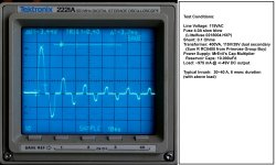
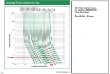
This is a repeat of the earlier tests, this time with a 400VA transformer, 35V secondary, Cap Multiplier PSU w. 10.000 uFd capacitors, 50V DC output, 1A constant load per rail. One of the pics shows a Time-Current diagram for a typical slow-blow fuse. In all tests the inrush seems well below the typical fuse rating.
The first picture is probably the most important, because it shows the worst case inrush, in terms of peak current, combined with worst-case duration. The magnitude of the inrush depends on the reservoir cap value and the load.
The second pic shows the time-current curve for the selected fuse.
The 3rd and 4th pics show another aspect of the current inrush, which results from the transformer alone.
The 3rd pic was taken with the transformer secondary winding disconnected from the power supply, so none of the inrush is due to reservoir caps charging in this case. The magnitude of the inrush depends on when power is switched on, relative to the zero-cross of the power line.
The 4th pic shows a combination of the two possible events, for illustration.
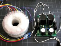
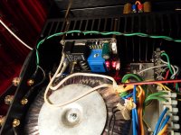
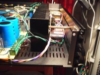
The last picture shows the transformer and power supply board used for the tests.
Comments are welcome, but I do not have any new insights from the tests, they show pretty much the same thing as the first set, with more detail.
(Continued from HERE)
This is a repeat of the earlier tests, this time with a 400VA transformer, 35V secondary, Cap Multiplier PSU w. 10.000 uFd capacitors, 50V DC output, 1A constant load per rail. One of the pics shows a Time-Current diagram for a typical slow-blow fuse. In all tests the inrush seems well below the typical fuse rating.
The first picture is probably the most important, because it shows the worst case inrush, in terms of peak current, combined with worst-case duration. The magnitude of the inrush depends on the reservoir cap value and the load.
The second pic shows the time-current curve for the selected fuse.
The 3rd and 4th pics show another aspect of the current inrush, which results from the transformer alone.
The 3rd pic was taken with the transformer secondary winding disconnected from the power supply, so none of the inrush is due to reservoir caps charging in this case. The magnitude of the inrush depends on when power is switched on, relative to the zero-cross of the power line.
The 4th pic shows a combination of the two possible events, for illustration.
The last picture shows the transformer and power supply board used for the tests.
Comments are welcome, but I do not have any new insights from the tests, they show pretty much the same thing as the first set, with more detail.
Attachments


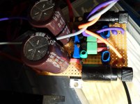
Just finished my P2P Cap Multipliers (one for each channel of the simple VSSA). One worked right away, on the other one I had troubles with some reversed lines between the amplifier MOSFETs and current mirrors (the fun of P2P). I picked this solution instead of using your nice PCB as I intend to mount them close to the modules and I have the main caps and speaker protection boards already. One step closer to VSSA experience 🙂
Cheers!
Cheers!
I look forward to seeing some pics! P2P is sort-of the ultimate DIY approach! 😀Just finished my P2P Cap Multipliers (one for each channel of the simple VSSA). ...
Pictures
Hi Pete,
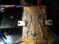
Not the greatest quality of the photos, but they might show the idea. It works perfect with my raw power supply (one trafo, one bridge and two caps (5600uF each) fed by a variac and a switchable bulb in series. The voltage drop over the series MOSFETs is around 700mV.
Cheers!
Hi Pete,
Not the greatest quality of the photos, but they might show the idea. It works perfect with my raw power supply (one trafo, one bridge and two caps (5600uF each) fed by a variac and a switchable bulb in series. The voltage drop over the series MOSFETs is around 700mV.
Cheers!
Attachments
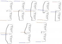
pics 1, 3, 6 & 8 are correct.Don't think so, but there's lot of wiring setups possible, some won't probably work, can it be wrong wiring setup that is choosen and takes fuse away ? See quick paintbrush drawing.
Pics 2, 4, 5 & 7 are wrong.
The bulb tester will show this.
The wrong wiring of pics 2, 4, 5 & 7 will at the very least blow the mains fuse. At worst these will blow up the transformer.
Even with the transformer not connected to the Rectifier, you must always ensure the correct phasing of the primary windings. This applies when wiring in series for 220/240Vac, or wiring in parallel for 110/120Vac.
I like it, and the board is about the right size to mount on the heatsink next to VSSA.Hi Pete,
Not the greatest quality of the photos, but they might show the idea. It works perfect with my raw power supply (one trafo, one bridge and two caps (5600uF each) fed by a variac and a switchable bulb in series. The voltage drop over the series MOSFETs is around 700mV.
Cheers!
Are you using the ground scheme recommended in the VSSA thread? In other words, do you have the VSSA boards grounded to the heatsinks, or isolated at the three mounting screws? (Mine is isolated now, except at the conventional single-point chassis connection.)
When you say sub-sonic, do you actually mean inaudible? Sub-sonic is almost synonymous with infrasonic which is a totally different thing.With this particular cap multiplier, the line sag at bass frequency will still show up at the first (main reservoir) cap. At the second (output cap), the line sag is filtered as a function of the RC constant in the cap multiplier. It is still there, but much smaller in amplitude. More important for me (personal preference only), the rail disturbance is pushed down in frequency to sub-sonic level (tested).
Thanks for decoding, the few times i tried use old unmarked transformers, i used variac watched current consume at meter and listened for buzzing from trafo, and by that got a connection wiring that could Work.pics 1, 3, 6 & 8 are correct.
Pics 2, 4, 5 & 7 are wrong.
The bulb tester will show this.
The wrong wiring of pics 2, 4, 5 & 7 will at the very least blow the mains fuse. At worst these will blow up the transformer.
Even with the transformer not connected to the Rectifier, you must always ensure the correct phasing of the primary windings. This applies when wiring in series for 220/240Vac, or wiring in parallel for 110/120Vac.
That bulb tester you mention, is there a link to see schematic for that setup.
In-audible, yes. Poor choice of words, I should have just said below the audio band.When you say sub-sonic, do you actually mean inaudible? Sub-sonic is almost synonymous with infrasonic which is a totally different thing.
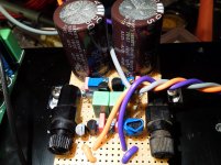
I like it, and the board is about the right size to mount on the heatsink next to VSSA.
Thanks! Indeed they are already mounted on the 300mm length x 80mm height heatsink side by side near VSSA modules. So each channel takes one heatsink, one VSSA and one cap multiplier.
Are you using the ground scheme recommended in the VSSA thread? In other words, do you have the VSSA boards grounded to the heatsinks, or isolated at the three mounting screws? (Mine is isolated now, except at the conventional single-point chassis connection.)
I will not ground the modules via the screws on VSSA. I have isolated two of them. (Actually the ALF hole in the VSSA PCB has no GND connection)
As a matter of fact I will not connect the chassis directly on any of the ground lines, but using a *DDRC connection from each ground to the chassis, taking the ground point from the middle point of the main filter caps.
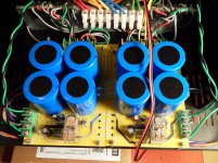
Some details of my build: I use a custom 500VA toroidal trafo from TOROIDY (a Polish company well known in Europe) that gives four separate main 28V and two independent 12V. The trafo is using more windings/Volt than a usual one, reducing the radiated field (so called oversized). The inner side (the support) is filled with a resin that prevents any kind of buzzing. I consider it a great trafo for this project.
Each of the 28V AC feeds a discrete bridge of soft recovery 12Amp diodes so no wire comes from the trafo directly in none of the L and R GND. Especially when using toroidal trafo's I like to avoid that, because they are known to be more transparent for parasites that can ingress from the mains.
Main reservoir caps are 8 Vishay 15,000uF/40V, so that is 30,000uF on each rail that supplies ~39V to each side of the cap multiplier. My pocket size scope shows no ripple at the output of the Cap multiplier even when decreasing the voltage drop to approximate 600mV so that is good news 🙂
Almost dual mono, but with a common Iron (the core of the trafo) 🙂
Until now I successfully adjusted one VSSA channel and I am working on the second one. After I am sure everything works properly on the bench for a few days (that will allow the CAPs to form too) I will try the sound as well.
Cheers!
*DDRC is known to me from Rod Elliot articles and it means two diodes mounted in anti-parallel and to this I paralleled a 10R/3W inductive resistor and a 0,1uF/100V cap. The diodes are part of the 25A bridge, the way of using it is quite intuitive, also shown on his site
I did not realize the ALF was already isolated, so I just used the same plastic shoulder washer everywhere. I think I will take that out now, the Alfets should have a good tight connection. I have seen that ground circuit on Rod's web site, I normally use almost the same ground scheme but w. discrete diodes.
Very interesting about the transformer!
I have seen similar transformers used in some medical instruments to reduce the magnetic field to essentially zero, but they are usually lower power, and too expensive for diy projects. I have a semi-custom transformer from the recent "Primrose" GB, but it has a mechanical hum, so I am using it just for testing the PSU right now. (Post 487 above)
Made in NL by hand, looks great......Not the greatest quality of the photos, but they might show the idea. It works perfect with my raw power supply (one trafo, one bridge and two caps (5600uF each) fed by a variac and a switchable bulb in series. The voltage drop over the series MOSFETs is around 700mV.
Cheers!
Thanks for detailed description of ideas for build. Looks forward result about you satisfied with sound, and even more if it's going bridged/ballanced from your JC-80 pre......they are already mounted on the 300mm length x 80mm height heatsink side by side near VSSA modules. So each channel takes one heatsink, one VSSA and one cap multiplier.....
.....Almost dual mono, but with a common Iron (the core of the trafo) 🙂
Until now I successfully adjusted one VSSA channel and I am working on the second one. After I am sure everything works properly on the bench for a few days (that will allow the CAPs to form too) I will try the sound as well.
Cheers!
*DDRC is known to me from Rod Elliot articles and it means two diodes mounted in anti-parallel and to this I paralleled a 10R/3W inductive resistor and a 0,1uF/100V cap. The diodes are part of the 25A bridge, the way of using it is quite intuitive, also shown on his site
BRYTT! Thanks for the nice words!
I think that is why we are here, to share our implementations and ideas 🙂
I finished both channels and left the big caps forming while thinking of the front panel. I need a momentary switch to stop-start the power supply and I don't have it in my inventory.
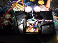
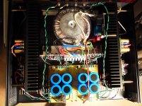
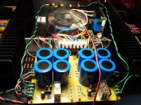
I have attached a few pictures to show the whole concept. I use ventilated covers, that is why I mounted the heatsinks inside, with amplifier modules and cap multipliers mounted between the walls and heatsinks. Of course, I will need to form all the cables to avoid that messy look.
The feet of the case are fixed with bolts in the heatsinks through the bottom cover.
The heatsinks are just slightly warm, with 180mA flowing through each VSSA module.
Will wait a few days till the sound check, and will start to think of an arrangement for a stereo balanced VSSA. Will definitely use there these cap multipliers.
Cheers!
I think that is why we are here, to share our implementations and ideas 🙂
I finished both channels and left the big caps forming while thinking of the front panel. I need a momentary switch to stop-start the power supply and I don't have it in my inventory.
I have attached a few pictures to show the whole concept. I use ventilated covers, that is why I mounted the heatsinks inside, with amplifier modules and cap multipliers mounted between the walls and heatsinks. Of course, I will need to form all the cables to avoid that messy look.
The feet of the case are fixed with bolts in the heatsinks through the bottom cover.
The heatsinks are just slightly warm, with 180mA flowing through each VSSA module.
Will wait a few days till the sound check, and will start to think of an arrangement for a stereo balanced VSSA. Will definitely use there these cap multipliers.
Cheers!
Attachments
Wao... thanks for teaser with those pictures. Lot of care is taken in your build in DC concern before it reach VSSA modules, it must pay back i really hope, and very good listening.BRYTT! Thanks for the nice words!
I think that is why we are here, to share our implementations and ideas 🙂
.....Will wait a few days till the sound check, and will start to think of an arrangement for a stereo balanced VSSA. Will definitely use there these cap multipliers.
Cheers!
- Status
- Not open for further replies.
- Home
- Amplifiers
- Power Supplies
- Finished capacitance multiplier