On the Subject of Pucks
I read with great interest the information and opinions on pucks given in the last pages. In particular, Peter Daniels comments and the link he suggested. What I took from it all was that the puck has different jobs.
1. The puck helps transfer torque from the motor table to the CD.
2. The puck holds the CD down on the motor table.
3. Sometimes, the puck helps control vibration in the CD. It is possible a bad puck can make vibration worse.
4. The puck needs to do all of this without adding too much strain to the motor and its bearings.
Of these functions, I am trying to understand their importance.
That sent me off to look at a couple of commercially produced approaches. The one that I found most interesting was in a Philips-Magnavox boombox I have around. That puck is molded plastic (Polystyrene maybe?) and doesn't have much mass. It is a hollow cylinder, about 28 mm in diameter with a pilot for the motor table center hole and cone. Around its outer edge, it has a ring of soft rubber that engages the CD.
Outside of this, there is a disc of flexible plastic sheet, probably less than 1 mm thick and 75 mm in diameter. On the bottom side of the disc, there is a ring of soft, cloth like fibers. My guess is that the disc and the fibers are intended to cover the laser when there is no CD. It is also possible that the disc and fibers provide some damping to vibration.
I like the idea of the soft rubber ring providing traction between the puck and the CD. I wonder why you wouldn't put rubber for traction on the motor table instead?
In the end, as Peter said, he has tried different kinds of pucks and the sound has been good. Maybe we shouldn't obsess too much and just use a simple puck.
Jac
CD Pucks
Jac,
The consensus is that a magnet Puck affects the CD laser servos...at least for the first few minutes when the laser is reading from the inside of the disc. But then again, Peter and other folks whose ears I trust have settled on various magnetic Puck.
My fall back is the magnetic CD Clamp I described...$3 for the magnet, which you could use as is with the right interface thickness spacer, and it self centers on the CD Turntable's molded in upper tapper. You can always add wood, plastic, etc to make it pretty and then obsess over whether it is perfectly balanced, while hoping the CD itself is also balanced. Based on the various manufacturing tolerances, good luck on the latter always being the case...but remember, it is only turning 500 rpm at the start and down to 200 rpm at the end.
I am also looking for a metal insert with a threaded ID that will fit into the Sanyo CD Turntable center hole. That would allow making a low mass screw-down Puck work. At a start-up speed of 500 rpm, not much clamping force is needed and with a rubber interface you suggested on the Turntable and Puck, there would be very little chance for slip.
So there are options. There are various manufacturers who will likewise sell you a CD Puck...mostly magnetic one. ARC, Naim and others come to mind.
It's a hobby...and addicting one, and up to a point some obsession is OK. But this transport is going to be killer...better than or at least the equal to the best available at any price...until Tibi, Peter or someone else comes up with something "better". That seems to always happen...
...
So there are options. There are various manufacturers who will likewise sell you a CD Puck...mostly magnetic one. ARC, Naim and others come to mind.
...
Naim puck will not work due inner hole is too small. Already tested by me.
Regards,
Tibi
@tivol When will the orders send to the customers?
Still waiting for LCD's to arrive from factory. Also, the PCB boards are still in production.
We expect to have trafo's, for those who ordered Shiga ready mounted and tested, at the end of next week.
The great news it that we were able to source a large batch of LC78601RE, maybe the last ones. 🙂
Regards,
Tibi
Can someone confirm if the EZ35 could be used?
Can not be used. See schematic
http://vicol-audio.ro/docs/jvc_rc-ez31bb,rc-ez35rb.pdf
Regards,
Tibi
The great news it that we were able to source a large batch of LC78601RE, maybe the last ones. 🙂
Regards,
Tibi
Fantastic news. Congratulations!
Tvicol,
THanks and good to hear. I know how much you have put into this and have nothing but the greatest of admiration for your efforts. It shows you have true passion for fine audio.
THanks and good to hear. I know how much you have put into this and have nothing but the greatest of admiration for your efforts. It shows you have true passion for fine audio.
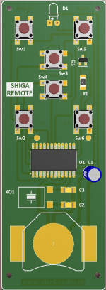
Remote schematic attached.
We are working on PCB and hope to offer this as well.
CD puck not yet defined. I´m still designing and looking for best looking/performance/value.
Regards,
Tibi
We are working on PCB and hope to offer this as well.
CD puck not yet defined. I´m still designing and looking for best looking/performance/value.
Regards,
Tibi
Attachments
Last edited by a moderator:
That is splendid news indeed! The Shigaclone project evaded demise once more thanks to your efforts 🙂...
The great news it that we were able to source a large batch of LC78601RE, maybe the last ones. 🙂
Regards,
Tibi
Short update to project status.
Today we have received the trafos.
We expect to have LCD displays delivered on 28. August
We´ll receive Shiga PCB boards on 31. August.
Remote IR boards are also in production and I expect to have them around 31. August as well.
As soon we get PCB boards we´ll start shipping for DIY and Full Shiga Kits.
Ready mounted and tested will take off in the first week of September.
Thank you for your patience and understanding.
Regards,
Tibi
Last edited by a moderator:

Tibi,
A question about the 5v circuit.
If I use a separate regulator for the 5v circuit and power it with batteries, leaving the 8v circuit (reg) to be powered by a mains transformer, couldn't that introduce some grounding issues? Do you think it would be better to leave both circuits powered by the same battery supply?
Hi all,
Please, I want to know if the output impedance on the DIGITAL out is about 235 Ohm? That's for calculate an ideal T-pad resistor circuit : attenuator about -10 dB and 75 Ohm output.
Thanks.
Please, I want to know if the output impedance on the DIGITAL out is about 235 Ohm? That's for calculate an ideal T-pad resistor circuit : attenuator about -10 dB and 75 Ohm output.
Thanks.
Because the output impedance have a hudge influence on the soundstage 'picture' and 'linearity' , specific of character of sound on solo instruments...!
I have really very good results with (after surching with all kind of possibility's ): 6K8 parrallel on direct ouput , 200 Ohm in series to output and 90 Ohm parallel to output : to now that's the best result I have , really nice !
But maybe that would be better ?
Some experiences ?
But maybe that would be better ?
Some experiences ?
These are some interesting comments you make sigurd, but I am a bit confused as to what actual resistor layout you are using - could you draw a schematic for us, or take a picture? You are saying you have two resistors to the ground + one series, but this sounds like a Pi-pad, not a T-pad?... I'm not nitpicking, just trying to making sure I understand you correctly.
The datasheet for LC78601 doesn't state this, but the digital output impedance is most likely 75Ohm, as per S/PDIF standard. Did you try the 75Ohm Pi-pad I suggested earlier? I built one with my hand-made resistors (which were accurate to +/-0.1R), and I found it to sound far superior to the original L-pad (the detail and resolution took a leap, in particular). I have not tried any further combinations because I assumed 75Ohm should be optimal... But of course, I will be the first to admit that in the audio world theory and practise are often two different stories.
The datasheet for LC78601 doesn't state this, but the digital output impedance is most likely 75Ohm, as per S/PDIF standard. Did you try the 75Ohm Pi-pad I suggested earlier? I built one with my hand-made resistors (which were accurate to +/-0.1R), and I found it to sound far superior to the original L-pad (the detail and resolution took a leap, in particular). I have not tried any further combinations because I assumed 75Ohm should be optimal... But of course, I will be the first to admit that in the audio world theory and practise are often two different stories.
- Home
- Source & Line
- Digital Source
- Finally, an affordable CD Transport: the Shigaclone story