Peter Daniel said:IIRC you need to unsolder the display pins first to remove it. The white bracket is attached with 2 screws and two clips. And don't forget about the LED, it's there too.
Hello all
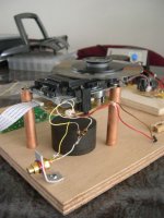
Is it possible to separate the display screen from the white bracket?
Thanks
Edit: Forgot to mention. What is the pourpose of the misterious component in the red rectangle on the left, connected to a black wire?.
Got the Wyde Eye cable today. This is a 75 ohm cable with real 75 ohm bnc connectors - they sell it as a word clock cable pn WE-BB. I have real 75 bnc on both the transport and the dac and the source and termination are actually 75 ohms - go figure. (I'm an EE..)
Anyway this set up sounds at least as good as the mystery prototype spdif (High end) cable I was given eons ago to evaluate which required kludgy adaptors to use with the bnc jacks on my gear.
Not too expensive compared to the usual high end cable tom-foolery, and it really does seem to be a little better than the very good cable it replaced.
Re: Re: Interested Check
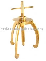
I am going to post a picture of the bearing puller that I use, inappropriate method of pulling out the platter will cause the shaft out of round of the shaft permanent !!
kevinkr said:
Sounds interesting, any possibility of a simple tool (puller) to prevent motor damage when removing the old platter?
I am going to post a picture of the bearing puller that I use, inappropriate method of pulling out the platter will cause the shaft out of round of the shaft permanent !!
YESSS...I soldered the 300/100 resistors in place...and received a beautiful lock...spot on.....
I bought a nice 2 x 8 V trafo CT and the blackgates FK 1000/35 and N 1000/50 as well as the MRS860 but then the MRS560
(according to the shops advice) and a heatsink and breadboard
so if it keeps raining I know what to do tomorrow....
I bought a nice 2 x 8 V trafo CT and the blackgates FK 1000/35 and N 1000/50 as well as the MRS860 but then the MRS560
(according to the shops advice) and a heatsink and breadboard
so if it keeps raining I know what to do tomorrow....
Attachments

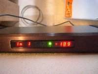
Erik van Voorst said:YESSS...I soldered the 300/100 resistors in place...and received a beautiful lock...spot on.....
I bought a nice 2 x 8 V trafo CT and the blackgates FK 1000/35 and N 1000/50 as well as the MRS860 but then the MRS560
(according to the shops advice) and a heatsink and breadboard
so if it keeps raining I know what to do tomorrow....
That's good news.. Should be interesting to see what effect the new power supply has on performance. The change was not that subtle in mine, and finally changing to BG on the output of the regulator was audible as well.
My digital interconnect is actually rather short, only 18" - I've tried longer cables and very long ones occasionally do perform better. Not sure when the reflection arrives back at the input receiver, but so far I have not heard audible degradation with a couple of very short cables I've tried.. Most of my commercial spdif cables are odd lengths, but I have tried standard 75 ohm coax in varying lengths and it was always worse sounding than any of the specifically spdif cables I have.. No real idea why, presumably a TDR would answer that question...
Must admit that with those resistors "The PitBull" becomes a different ballgame...!!!!!!!!!!
I am really enjoying cd after cd and finally can understand the hype....you simply can here the potential...IT IS THERE...
I most definitely am going to invest time and money...

I am really enjoying cd after cd and finally can understand the hype....you simply can here the potential...IT IS THERE...
I most definitely am going to invest time and money...
Re: Re: Re: Interested Check
Hi
Here is a picture of puller for you:
clearaudio said:
I am going to post a picture of the bearing puller that I use, inappropriate method of pulling out the platter will cause the shaft out of round of the shaft permanent !!
Hi
Here is a picture of puller for you:
Attachments
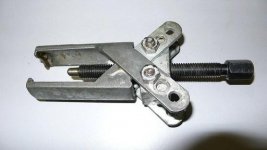
That is the right tool....
BTW I hope Okapi will take orders in a group buy what he mentioned earlier on otherwise I am most certainly interested in your offer...anyway I am interested in your pics of the clamp..
Peter are you using Okapi's clamp at the moment or are you also waiting untill Okapi finds time to help out....
BTW I hope Okapi will take orders in a group buy what he mentioned earlier on otherwise I am most certainly interested in your offer...anyway I am interested in your pics of the clamp..
Peter are you using Okapi's clamp at the moment or are you also waiting untill Okapi finds time to help out....
my clamp progress has been slowed by a lot of work related travel. i have been in okinawa for three weeks and shortly after i return i am off to colorado for a week.
i am concerned that the center bore is not running straight on the clamp. with such a long and narrow bore the tool might be pushing off center. i need to quantify this problem and possibly make some design changes before i proceed.
i am concerned that the center bore is not running straight on the clamp. with such a long and narrow bore the tool might be pushing off center. i need to quantify this problem and possibly make some design changes before i proceed.
Erik van Voorst said:That is the right tool....
BTW I hope Okapi will take orders in a group buy what he mentioned earlier on otherwise I am most certainly interested in your offer...anyway I am interested in your pics of the clamp..
Peter are you using Okapi's clamp at the moment or are you also waiting untill Okapi finds time to help out....
In my opinion, a three leg pulley clamp is better still. Reason behind is the bending stress is well evenly distributed, think can get a cheap one from a local hardware shop. This Three leg gear puller is from China. USD10??
Attachments
Which -51 builder can help...
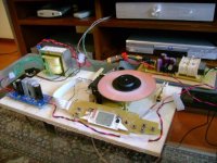
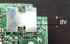
I have build a dedicated powersupply 8 Volts and fed it direct to the motor (on the choke position).
I also fed the led with 5 Volts direct (orange and grey wiring)
By doing so I could remove the main board and ps board...
When firing up....the disc started to turn like mad...searching.......and stopped.....and the led whas not lit....
Measuring and checking and everything was okay
Hi Erik,
Lets start with the LED, orange wire is NEGATIVE and the grey wire next to the orange is positive. You will need to add a series resistor as well.
If you have 8 volts and the polarity correct, I can't see why you will have a problem with the transport..
Lets start with the LED, orange wire is NEGATIVE and the grey wire next to the orange is positive. You will need to add a series resistor as well.
If you have 8 volts and the polarity correct, I can't see why you will have a problem with the transport..
Attachments
Erik van Voorst said:Thanks for such quick reply
If You mean the 10K I have done that...
I will check polarity again tonight...
Erik, your LED may not be working because the voltage is to low. The 10k resistor is based on having up to 25v of supply. If you have a separate 5v supply, then 1k is more than enough..
- Home
- Source & Line
- Digital Source
- Finally, an affordable CD Transport: the Shigaclone story