Hello Tibi,
I would be interested for the main board and modded CD mechanic but with 24% VAT to France the total price is too high for me in this Christmas period.
As i already own a MK1, do you think the modded CD mechanic only could be a good upgrade ? better than change only the board?
I would be interested for the main board and modded CD mechanic but with 24% VAT to France the total price is too high for me in this Christmas period.
As i already own a MK1, do you think the modded CD mechanic only could be a good upgrade ? better than change only the board?
Hi, if anyone is fancy to buy parts for Shigaclone pls let me know as I have just found my unfinished project in box.
Hi everybody. I'm on the progress build shigaclone with vicol board. I think the first edition board (the green one) i confusing how to using minireg LT1763 5v for local reg V3 and V4. For V4 i understand i must remove L4 and L5. But how to using minireg for V3 ? Which ferrite bead i must remove?
When I'm using miniregs for v3 and v4 i still can supply v1 and v2 with onboard 8v input right? Thank you for your support.
When I'm using miniregs for v3 and v4 i still can supply v1 and v2 with onboard 8v input right? Thank you for your support.
All documentation related to first Shiga is available at this page vicol audio : shiga CD transport
Also detailed construction is available here https://docs.google.com/document/d/1vlabZc_1If3x12ox2A5ECZxC0HLGnuOWdM-j9X4b7Q0/edit
Kindly read and digest.
Regards,
Tibi
Also detailed construction is available here https://docs.google.com/document/d/1vlabZc_1If3x12ox2A5ECZxC0HLGnuOWdM-j9X4b7Q0/edit
Kindly read and digest.
Regards,
Tibi
All documentation related to first Shiga is available at this page vicol audio : shiga CD transport
Also detailed construction is available here https://docs.google.com/document/d/1vlabZc_1If3x12ox2A5ECZxC0HLGnuOWdM-j9X4b7Q0/edit
Kindly read and digest.
Regards,
Tibi
Thank you for your guidance Tibi. I confused about V3 supply because i look at the schematic and I was thinking to remove L3. I will remove L4 and L5 and use minireg for V3 and V4. Regards
A limited batch of 20 units Shiga MKII will be available for sale starting from 1st March. Few high grade modded CD mechanics will be available as well.
Regards,
Tibi
Regards,
Tibi
tvicol,
How is your friend Andrei doing with regards to his 3D printed CD player? Has he finished the Mark 2 version in wood and carbon fiber?
How is your friend Andrei doing with regards to his 3D printed CD player? Has he finished the Mark 2 version in wood and carbon fiber?
tvicol,
How is your friend Andrei doing with regards to his 3D printed CD player? Has he finished the Mark 2 version in wood and carbon fiber?
Seems you know more than me. 😉
I'll ask him.
In the mean time you may enjoy Quantum.
Regards,
Tibi
Maybe something interesting
I saw an ad on eBay. Might be interesting for those looking for original JVC drive (BTW I'm not the poster):
JVC RC EZ31B FOR A Special TOP END Audio Drive | eBay
I saw an ad on eBay. Might be interesting for those looking for original JVC drive (BTW I'm not the poster):
JVC RC EZ31B FOR A Special TOP END Audio Drive | eBay
Sanyo SF-101 cd mechanism issues
Although I have not actually built a Shigaclone construcction I have been following this thread because I use a 47 Lab Shigaraki CD transport, which was the inspiration for this project.
So, maybe can help me here. Lately I have been having issues -skipping and distorting- with the mechanism reading some CD's. Basically I have some CD's which are read completely by my Oppo 93 without any issues and these same CD's have problems with various tracks when played in the Shigaraki. One of them is practically new.. I cleaned it and got a little better...
I replaced the mechanism and also the ribbon connector but it keeps doing the same. I have examined the CD's in question and there are no major scratches in them, at least visible with the naked eye..
This mechanism is the 15 p one, not the 16 p you guys use in the Shigaclone..
So my question is: is this laser or mechanism that sensitive reading CD's or is there something else wrong?
...
So my question is: is this laser or mechanism that sensitive reading CD's or is there something else wrong?
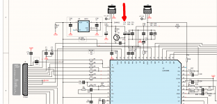
I suggest you to replace laser CCS capacitor to a high quality tantalum one, as we use in Shigaclone.
This should clear your reading issues.
In Shiga MKII this is marked C19 and is 47uF/6V - see attachment arrow.
You need to find equivalent capacitor in Shigaraki.
Regards,
Tibi
Attachments
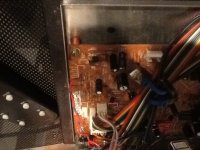
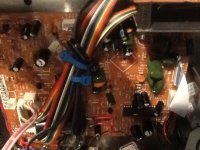
Thanks. I looked into the board and the chip is the same as you show above, but I could not identify the cap you refer to. There are no regulators around that chip. The only ones are at the input of the AC, one for 8v and another for 5v. There are a bunch of electrolytic caps around the chip area and ribbon input -and some green film ones. One of these has a value of 15K written on it-. I will post a photo of the area.
Follow the trace from LA9242M pin 62. The cap should be between 33uF to 100uF and is near to a 2SA608N transistor (in my schematic Q1 - 2N4403)
Regards,
Tibi
Regards,
Tibi
Manolo47,
If you want to get help, you need to provide more than a blurry image.
Remove the board and make macro pictures at high quality, in order to see traces and parts values. Details matter.
Regards,
Tibi
If you want to get help, you need to provide more than a blurry image.
Remove the board and make macro pictures at high quality, in order to see traces and parts values. Details matter.
Regards,
Tibi
- Home
- Source & Line
- Digital Source
- Finally, an affordable CD Transport: the Shigaclone story