Did some more listening and I think its clearer for me... Paper tape under Tibi's puck is a nonono.
Hi Tibi,
I have the CD Puck ordered.
Might be an option, boards of the 5v Salas low voltage shunt regulator because dimkasta have good results with those regs.
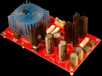
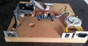
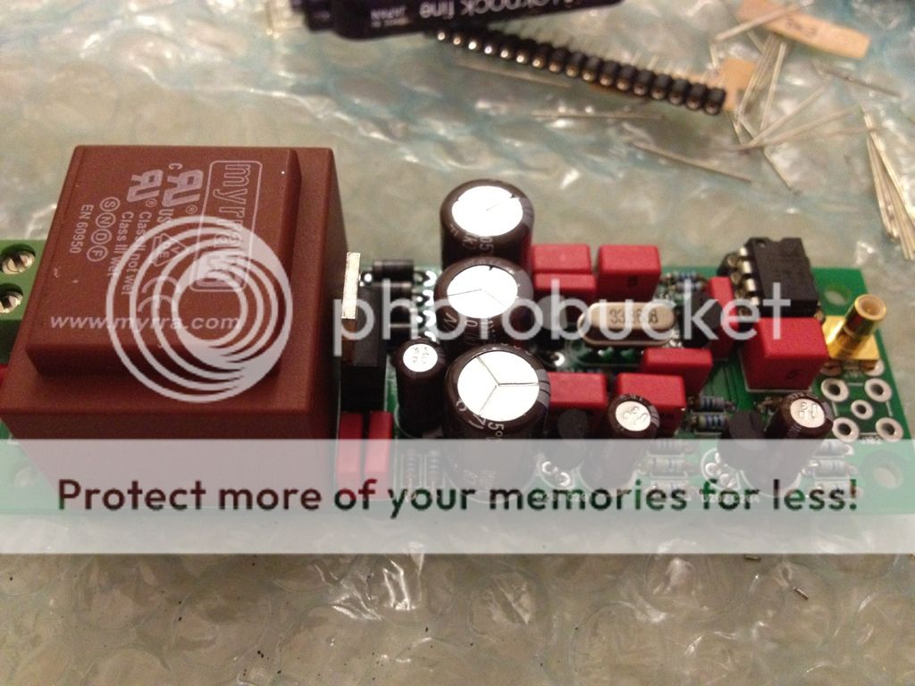
Here a picture of Doede his site this is how I mean inclusive the transformer, plug in and play.
These are 5v 1A regs, I think that 80mA will be enough.
Only the 2 motor has more power needed.
Regards,
Rudy
I have the CD Puck ordered.
Might be an option, boards of the 5v Salas low voltage shunt regulator because dimkasta have good results with those regs.
Here a picture of Doede his site this is how I mean inclusive the transformer, plug in and play.
These are 5v 1A regs, I think that 80mA will be enough.
Only the 2 motor has more power needed.
Regards,
Rudy
Attachments
Last edited:
No one can help me with this question? 😕
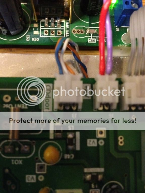
If I connect this +5v wrong I have a problem, I would like to know for sure.
Regards,
Rudy
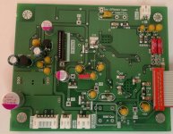
The orange wire is the 5V which connects the main pcb and the display pcb.
Thanks syklab,
Waiting now for the terminals, when they arrive I go further.
I have no hurry because I can listen every day, to my Shigaclone.
The only goal for me is to make Tibi’s Shiga better sounding.
Regards,
Rudy
Waiting now for the terminals, when they arrive I go further.
I have no hurry because I can listen every day, to my Shigaclone.
The only goal for me is to make Tibi’s Shiga better sounding.
Regards,
Rudy
Attachments
Last edited:
Hi Skylab,
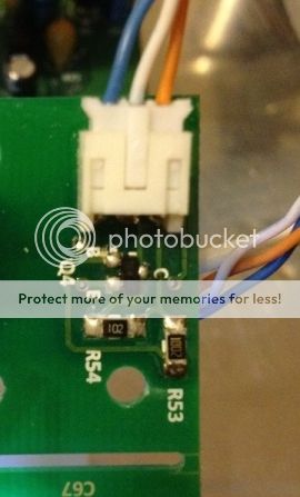
I look again to your picture and see you use red for GND and purple for +8v 😕
Be aware you make no mistakes with diferent colors.
The other side of the PCB is +8v, on the wrong side the intention was, here the + 8v connection.
Then the error thus made
I have changes the inlet with a fuse 😉
Regards,
Rudy
Attachments
Last edited:
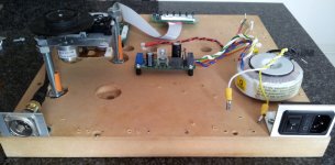
I inserted the cable in the wrong direction, the blue is +8V and reed is ground, I have marked te red cable with a black marker so I won't forget. I will make a correct cable later.
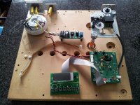
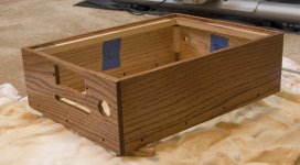
Nothing special to show, except my enclosure (sans top). It is currently drying from its final coat of semi-gloss polyurethane. I decided to stain it Cherry. Looks better in person than in the pic.
You can see that because the cabinet walls are thicker than a standard aluminum enclosure I had to cut a slot for the buttons instead of small holes - the buttons would have never cleared the wall thickness that way. I don't have a router, so I couldn't route out the backside to help.
Considering the last time I did any hobby woodwork was in high school shop class I guess it's not horrible.
Attachments
Hi Syklab,
Did you get the chance to replace the clock with Anton's kit?
I aso have the same kit and eager to hear your impressions.
Thanks!!
Did you get the chance to replace the clock with Anton's kit?
I aso have the same kit and eager to hear your impressions.
Thanks!!
Hi Syklab,
Did you get the chance to replace the clock with Anton's kit?
I aso have the same kit and eager to hear your impressions.
Thanks!!
I just finished building the kit and it is 4am now so I will try to test it tomorrow and see how it works, I don't have a scope to test it so I will check if there is a 5v presented in the clock output. I will need to buy a scope soon!
I have built 2 UGG super reg for 8V and 5V plus the TPS7A4600 for 5v as well. Next thing may be test it with separate PS for 8V and 5V.
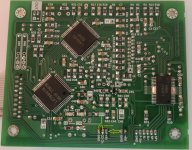
Clock module
+8V Super reg
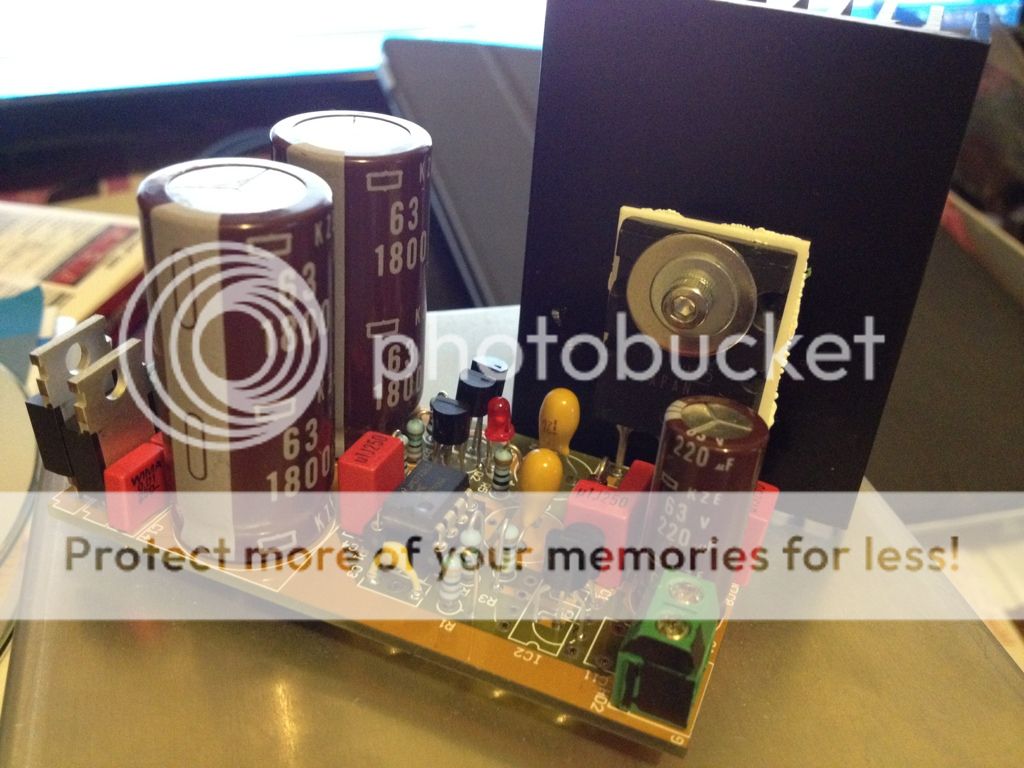
Is that your clock (at 33 Mhz)...or a borrowed photo
3 crystal were supplied with clock kit:
11.2002, 16.9344 and 33.8638
I just had the 33.8638 in the socket for the time being, I will replace it with the 16.9344 before I hock it up to the Shigaclone.
Yeah I figured something like that 😉
Today I upgraded the Mini-PiTbull Mark I with the Studio Zey Invisistors.


They replaced the Allen Bradleys....speaking of nobrainers 😎
Today I upgraded the Mini-PiTbull Mark I with the Studio Zey Invisistors.
They replaced the Allen Bradleys....speaking of nobrainers 😎
It all depends on the definition of "huge"....
Let's say I heard a difference I was willing to pay for..😉
I did not expect that they also outperformed the Vishays but to my ears they did...so happy me
Let's say I heard a difference I was willing to pay for..😉
I did not expect that they also outperformed the Vishays but to my ears they did...so happy me
skylab, is that a Teddy super-reg?
That's a UCC mini gold super reg from Taiwan.
All that's left is the top and attaching the lexan cover in front of the display. The lexan has already been cut, will be drilling the through holes later today. The top might be easier now that I think I have the right tool for the job.
Figured a couple of updated pics would be in order.
Figured a couple of updated pics would be in order.
Attachments
- Home
- Source & Line
- Digital Source
- Finally, an affordable CD Transport: the Shigaclone story