Messing around with my picoscope.... 😕
Doing some square wave analyses direct from the unbuffered outputs of the dam using some of my favourite filters. 😀
For the time being using only 1khz squarewave and volume control. Some filters reach clipping already at V=1. At V=0 they all seems ok.
These are the filters tried. The images are in this order.
1021filt_1013_C180_MP
1021filt_1015_C150_BW
1021filt_1015_Kb16_BW
bamb_comb
new_nos
Nothing surprising here it seems 🙂
BTW: I am quite novice here....
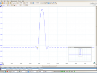
Wowzors, that new_nos 1 kHz square wave is pretty impressive. Seems like a near perfect square wave - no filtering of any (significant) second orders. I guess that's probably an obvious result to most but I haven't had much practical experience with NOS DACs.
What's the disadvantage of NOS with this DAC? I'd of expected aliasing distortion to be evident but it doesn't seem to be. Since rolloff doesn't seem there either. Is all this extra ultrasonic content bad for speakers? Otherwise, seems like NOS is super.
Last edited:
Please disregard prior post. I can't seem to edit it any longer. I've rewritten it to be clearer with my message.
Wowzors, that new_nos 1 kHz square wave is pretty impressive. Seems like a near perfect square wave - no attenuation of higher order harmonics. I guess that's probably an obvious waveform to most but I haven't had much practical experience with NOS DACs.
What's the disadvantage of NOS with this DAC? Typically people mention NOS disadvantages such as:
- Aliasing. But I don't seem to see any evidence of aliasing distortion.
- Sinc rolloff. But again, don't see any attenuation of high frequency components (no visible gibbs phenomenon).
Am I missing something?
One possible issue is that there is a lot of ultrasonic content in that signal. I presume that will be bad for the speakers, and possibly distort audible frequencies via IMD?
Otherwise, that NOS signal seems super.
There is some interesting speculative discussion on the polarity issue on the AudioGeorge website...
www.audiogeorge.com
That's the source where this recording issue started .. 😀
I understand that many will not come to this point or get the same conclusion, while it requires a good amp and speaker system.. Also all my CD's are re-burn with a F1 Yamaha Master Mode 1x speed using black CD-R surfaces... As I mentioned specially freq. above 1..4 kHz is the most sensitive range...😱
Cheers
Hp
Hp
Doing some more measurements.
From this website
Professional Online Audio Frequency Signal Generator
I downloaded a couple of 5sample sine pulse files. On ordinary and one with phase inverted.
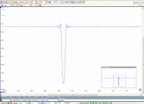
Using filter 1021filt_1015_Kb16_BW this is captured from the scope with
1. pulse - normal phase
2. pulse - inverted phase.
The dam - unbuffered outputs into a 10k load (amplifier).
Yes - the dam is inverting phase
From this website
Professional Online Audio Frequency Signal Generator
I downloaded a couple of 5sample sine pulse files. On ordinary and one with phase inverted.
Using filter 1021filt_1015_Kb16_BW this is captured from the scope with
1. pulse - normal phase
2. pulse - inverted phase.
The dam - unbuffered outputs into a 10k load (amplifier).
Yes - the dam is inverting phase
Attachments
Last edited:
If this can be switched easily this is a REALLY BIG DEAL!
Unfortunately it's not a DAM feature as far as I can see. I'm using the balanced outs, and may have swapped polarity when I was putting the DAC in a different box and changed to using off-board XLR's.
I'm using Audirvana+ and Pure Music on OSX for playback. The both have a method to change global polarity that requires stopping playback and altering a setting in much the same way as JPLAY. However both programs also recognise an "invertpolarity" tag in the file comments so you can do track by track switching.
I agree - I thought upsampling pushes the aliases apart (centred around new Fs) which allows you to design and implement a simpler analogue filter. I.e. the cutoff band/steepness no longer needs to be as strict as the aliases are 'further away'.
It doesn't push them apart. You are being mislead by the Analog Devices documentation which basically treats the upsampling DAC as a "black box" and focuses only on analog filtering the output. The assumption is that any digital filtering is done either prior to, or internal to the DAC.
It would be easy to change the polarity (globaly), you just need to multiply with -1 somewhere (e.g. the FIR2 coefficients).
It would be easy to change the polarity (globaly), you just need to multiply with -1 somewhere (e.g. the FIR2 coefficients).
Or in my case, swap the wires on the XLR headers so they are hooked up the right way around. 😱
No, you can't do that with SE.
In SE "-" is ground, it has no signal.
But you can do it in most players.
For foobar there's a plugin Simple Polarity Inverter.
dam1021,352800,1,1,1,1
Input FIR, 352.8 Khz Samplerate, Bypass
1.000
dam1021,384000,1,1,1,1
Input FIR, 384 Khz Samplerate, Bypass
1.000
In SE "-" is ground, it has no signal.
But you can do it in most players.
For foobar there's a plugin Simple Polarity Inverter.
Will it invert polarity if in the filter txt files the following 1.000 is changed to -1 ?It would be easy to change the polarity (globaly), you just need to multiply with -1 somewhere (e.g. the FIR2 coefficients).
dam1021,352800,1,1,1,1
Input FIR, 352.8 Khz Samplerate, Bypass
1.000
dam1021,384000,1,1,1,1
Input FIR, 384 Khz Samplerate, Bypass
1.000
Last edited:
My mind was not right 🙂
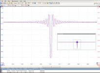
Here are both channels.
1 non-inverted sample pulse.
Channels not in "sync" and inverted.
BTW: I read here that my measurements are "not" correct according til Søren.
http://www.diyaudio.com/forums/vend...magnitude-24-bit-384-khz-272.html#post4332606
I will check my other equipment. Running RPI2 via USB to a gustard U12 (usb-i2s) lvds mode to the dam.
Will test with spdif also.
Attachments
Last edited:
You have to multiply by -1 all coefficients of one filter you use.Will it invert polarity if in the filter txt files the following 1.000 is changed to -1 ?
dam1021,352800,1,1,1,1
Input FIR, 352.8 Khz Samplerate, Bypass
1.000
dam1021,384000,1,1,1,1
Input FIR, 384 Khz Samplerate, Bypass
1.000
Your example would only be OK if you play 352.8 or 384 Khz.
The simplest is to change both FIR2, as they are always used.
It doesn't push them apart. You are being mislead by the Analog Devices documentation which basically treats the upsampling DAC as a "black box" and focuses only on analog filtering the output. The assumption is that any digital filtering is done either prior to, or internal to the DAC.
You're right spzzzzkt thanks for being patient with me 😛 so much to read up on...
Thanks, I found it, the FIR2 has a '2' as 4th parameter:The simplest is to change both FIR2, as they are always used.
dam1021,384000,8,2,113,8
Final FIR, 384 Khz Samplerate 0-100 Khz +- 0.01 db, 240 Khz -80db
...
dam1021,352800,8,2,113,8
Final FIR, 352 Khz Samplerate 0-92 Khz +- 0.01 db, 220 Khz 80 db
...
Last edited:
Guess we are stuck using a transformer and a switch.
Or another balanced line stage after the single-ended output. For those of us with op-amp phobia!
Well, it was exciting while it lasted ... Thought you were doing something with the UMANAGER.
In my system the DAM in single ended has much more output than I need so it might work out. Good transformers are not cheap - a toss-up between the two approaches. The transformer has the advantage of not taking up much space.
Take care,
Please disregard prior post. I can't seem to edit it any longer. I've rewritten it to be clearer with my message.
Wowzors, that new_nos 1 kHz square wave is pretty impressive. Seems like a near perfect square wave - no attenuation of higher order harmonics. I guess that's probably an obvious waveform to most but I haven't had much practical experience with NOS DACs.
What's the disadvantage of NOS with this DAC? Typically people mention NOS disadvantages such as:
- Aliasing. But I don't seem to see any evidence of aliasing distortion.
- Sinc rolloff. But again, don't see any attenuation of high frequency components (no visible gibbs phenomenon).
Am I missing something?
One possible issue is that there is a lot of ultrasonic content in that signal. I presume that will be bad for the speakers, and possibly distort audible frequencies via IMD?
Otherwise, that NOS signal seems super.
RE: NOS- early on Søren said that he had, "seen the aliasing and its not pretty". I haven't seen this come up in any of the measurements on this thread so far. Can anyone confirm this or is it all theory?
Side- I would like to get an inexpensive scope so that I can take measurements and contribute more here. Any suggestions?

See Paul's measurement in post #1055 for the aliasing products.
I think to be able to deal with all the high frequency components, the downstream components from preamp/buffer to amp to speaker/headphone needs to have very low IMD unless filtering is done.
I am pretty happy with The Wire Headphone Amp and HD800 in balanced mode. This could be because LME49990 and OPA1632 are both high bandwidth high slew rate parts with extremely low IMD.
This makes me wonder of using transformer due to its natural high frequency filtering, but I am not sure about the IMD of transformers.
Anyway this may be a little off topic. If we want to discuss further maybe we should move to other discussion threads on the forum.
Not sure if this is appropriate for this thread, but I came across 'exact interpolation' as part of my own research following discussions here. Zfe, spzzzzkt have you fellows come across this exact interpolation process? I.e. time domain -> FFT -> zero pad FFT -> inverse FFT resulting in up sampled time domain signal (exact interpolation values and keeping of original samples) as opposed to estimated interpolation samples based on accuracy of FIR filters.
I ran some basic/simple code to confirm the maths and it seemed to work well (based on random number generated waveforms).
Info here:
How to Interpolate in the Time-Domain by Zero-Padding in the Frequency Domain | dspGuru.com
filters - Upsample data using FFTs. How is this exactly done? - Signal Processing Stack Exchange
I understand that embedded DSP chips may not have the horsepower for this process, but I'm thinking is it worthwhile undertaking this upsampling process in PC and running the DAC in NOS mode?
RE: NOS- early on Søren said that he had, "seen the aliasing and its not pretty". I haven't seen this come up in any of the measurements on this thread so far. Can anyone confirm this or is it all theory?
Side- I would like to get an inexpensive scope so that I can take measurements and contribute more here. Any suggestions?
Aliasing - in it's strict sense - only occurs in ADC's when a signal in not properly bandwidth limited to below nyquist. In this case any content above the nyquist frequency is aliased below nyquist - in the case of 44.1kHz this means the aliasing will be audible. I'm yet to see anyone advocate for a NOS ADC, and with good reason.
With DAC's the opposite occurs. Content within the audio band mirrors around nyquist, and as the rate of oversampling the number of images increases. At x1 you have the original audio + 1 mirror image, at X8 you have the original audio + 15 mirror images. This is also often described as "aliasing" which muddies the waters.
The role of the reconstruction/image-reject/anti-alias filter is to remove the mirror images above nyquist. The brick wall filters attempt to meet the Nyquist-Shannon requirement of having no mirror images above nyquist - with varying degrees of success.
NOS on the other hand does no filtering at all, beyond the inherent sinc roll-off, and therefore retains all the mirror images (or aliases if you prefer) above nyquist.
Not especially. PC based resampling is discussed at length on any number of fora. As far as i'm aware this is the only thread that is dedicated to onboard filters for the DAM.Not sure if this is appropriate for this thread
My preference is that this thread stays focused on the onboard filters.
- Home
- Source & Line
- Digital Line Level
- Filter brewing for the Soekris R2R