It is clearly an open connection somewhere from the panel mount RCA jack to Molex female connector that plugs into the amp board. Wires in general don't go bad so let's concentrate on the solder joint at RCA panel jack to the wire, or the from wire to the Molex crimp connector. It is one or the other. My guess is a bad crimp connection on the Molex. A strain induced break at the solder joint of the RCA is the other possibility.Checked continuity from rca input to molex pins. Continuity on gnd from rca to molex gnd pin. No continuity from rca + pole to molex + pin
The good news is that the amp board works and this is a just a matter of replacing the input wiring. The fault is in this section: RCA jack / wires / Molex KK connector.
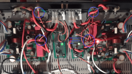
You may have a break in the solder joint beneath the red shrink tube wrap. The Molex connector at the PCB doesn't look right - it should look like the white ones on the SSR. The wires look too thick - possibly cannot get crimped properly. 21ga is good here.
Also, several close up oblique views at an angle and not straight from above often gives more information than a top down view which has many things blocking the open view. Fo example, this is an oblique view of this board so we can clearly see the type and quality of the connectors and joints. I think I am using JST connectors here since I ran out of Molex KK's.
Attachments
Last edited:
Sorry guys,
wiring harness = female housing with crimps inside.
molex connector = male header soldered to pcb.
See pics of both below


wiring harness = female housing with crimps inside.
molex connector = male header soldered to pcb.
See pics of both below
Agreed, trouble from the rca input to the molex connector at the pcb.
Molex connector at the pcb may be different looking in size, but it works just fine on the working channel.
Attached are the connection pieces I am using.

Molex connector at the pcb may be different looking in size, but it works just fine on the working channel.
Attached are the connection pieces I am using.
Hi Myles,
I don’t think you have inserted the crimped connectors in properly. They are not deep enough, hence not making contact with the pins. There should not be any metal of the crimp connector visible if it has been inserted all the way. You should hear and feel a click when inserting the crimped connector (with wire) into the plug. It should lock and not pull out easily. There is a correct orientation to the pin (0 vs 180deg). There is a locking barb and that needs to face the side of the shell with a little window.
Here is yours:

Here is one of mine:

Note that all you can see is wire and the shell.
I don’t think you have inserted the crimped connectors in properly. They are not deep enough, hence not making contact with the pins. There should not be any metal of the crimp connector visible if it has been inserted all the way. You should hear and feel a click when inserting the crimped connector (with wire) into the plug. It should lock and not pull out easily. There is a correct orientation to the pin (0 vs 180deg). There is a locking barb and that needs to face the side of the shell with a little window.
Here is yours:
Here is one of mine:
Note that all you can see is wire and the shell.
Thanks for all the help. I have re-soldered and re-crimped the input wires from the rca jack to the amp board and we have success. Music is playing from both channels and that makes me very happy. I am sure it also makes you happy, as no more questions should be forthcoming. I am letting the amp play for a while to let it settle in.
Some of the most important things I have learned is how important proper soldering practice is. I was using way to much solder, and not getting the solder to where it did any good. Proper crimping tools and techniques for these small gauge wires cannot be overstated. Testing procedures, well I am grateful for folks that have more building experience than me, and are willing to share their knowledge, so rookies like me do not blow up our projects to often.
Most of all, the enormous amount of help I have received from all the knowledgeable people here on the forum. I could not have gotten to the end of this journey without all your help. Thank you all. I know I will enjoy this amp for quite a while, and I thank xrk971 for the chance to build it. I will place the enclosure around the frame in the following days, and I will post some pics.
Next in line is the Xmas amp😀.
Myles McDonald


X, thanks for the tips on the crimp connectors. The housing's I have were to short for the regular crimp contacts with the barbs,(thought I might be able to get them to work) and they did not click in. Hence, i am using the crimp contacts with the metal loop (cats ear) on the bottom. They insert all the way and are solid. I will be ordering more housings soon and will make sure I get the correct ones needed to fit the barbed style.
Thank you,
Myles
Thank you,
Myles
You are welcome. Note that genuine Molex KK housings are mostly gone due to global parts shortage. No more stock. But plenty of Chinese clones on AliExpress.
It is outrageous, I just had some parts shipped from mouser last week for some BTSB molex connectors I ordered in April 2021!You are welcome. Note that genuine Molex KK housings are mostly gone due to global parts shortage. No more stock. But plenty of Chinese clones on AliExpress.
Get well soon buddy and don’t panic and worry you will be alright soon.Good news is that after changing wires to RC silicon wire, which is so easy to work with, I powered up one channel and adjusted to 26mv bias and had 8 mv on the output. Powered up the 2nd channel and adjusted to 26mv and had 2.0 mv on the output. Powered on both channels, and the amp is settling in around the 26mv bias range. Will hook up instant off board and the Gen1 RTRSSR boards, and populate the rear panel with the inputs and outputs.
Bad news is that I tested positive for Covid. How is a mystery to me, I had no problems in Mexico, it was very safe there. I come back to the Mountains and isolation, and I pick it up. What gives with that. It seems to be like a flu or a bad cold.
One other good thing is that it keeps me at home, so I can spend time finishing my projects. 👍
MM
MM,
Congratulations on getting the amp up and running!
As they say, now sit back and "enjoy the music"... 🙂
Congratulations on getting the amp up and running!
As they say, now sit back and "enjoy the music"... 🙂
So far X, it sounds very excellent, neutral, great dynamics, loads of power available. Seems very clean from the start up > forward, no burps, thumps, farts, etc. My leftover def tech inwalls are serving me as my basement / garage type speaker, so mid fi quality. Using amazon HD through my laptop. The pre I am using is my iDecco integrated amp which has a decent dac and a tube front end that can be activated / or not depending on your preference.
I went the cheap route on the enclosure and heat sinks,(for this amp & the Xmas amp) using what I had laying around, so the workmanship is not the best. Learned a lot about trying to make out of separate plates or searching for pre-formed enclosures at a cheap price. I am sure in the future I will find a better enclosure for the amp. Will post pics soon. Need to clean up my working area before pics. Bottom line, I could not be happier for my 1st attempt.
I went the cheap route on the enclosure and heat sinks,(for this amp & the Xmas amp) using what I had laying around, so the workmanship is not the best. Learned a lot about trying to make out of separate plates or searching for pre-formed enclosures at a cheap price. I am sure in the future I will find a better enclosure for the amp. Will post pics soon. Need to clean up my working area before pics. Bottom line, I could not be happier for my 1st attempt.
Great to hear that you like the sound, Myles. Ever since I gave my Griddle Amp (with FH9HVX) to a good friend, I miss having it.
SSR is working as planned, no turn on/turn off thumps. I have a slight hum from each speaker which I will hunt down, when I have more time. I have attached some pics of my home made enclosure (no laughter allowed 😡 ). The amp will get a better home in the future. Just enjoying having some tunes while working in the basement. One more homemade chassis for the Xmas amp, and then I can look for some better chassis.


- Home
- Group Buys
- FH9HVX - Budget Conscious 100w Class AB for Lean Times