What is the maximum safe rail voltage with a 4 ohm load?
Would these be safe with +/- 42-50vdc?
Would these be safe with +/- 42-50vdc?
As I am slowly assembling my boards, I noticed R132 and R134 have two sets of pads, and wondered if there would be any worthwhile sonic improvement by putting in Mills MRA05 resistors in place of the KOA BPR58's?
In the near future I'll be picking up some caps for another project and could grab some MRA's then. If no one has tried these yet I would be more than happy to be a guinea pig, that is unless X or someone else has a reason why MRA05's shouldn't be used in place of the BPR58's
In the near future I'll be picking up some caps for another project and could grab some MRA's then. If no one has tried these yet I would be more than happy to be a guinea pig, that is unless X or someone else has a reason why MRA05's shouldn't be used in place of the BPR58's
Mills MRA are wirewound resistors. KOA BPR are bulk metal resistors. They both work well but based on my testing, non wirewound resistors are typically lower distortion. Metal thin film are the lowest. Wirewound ceramic are the worst along with cement filled wirewound. Thick film metal oxide are not as good as metal thin film. Although I cannot positively be sure as I have not tested Mills MRA as a source resistor.
Mills MRA are wirewound resistors. KOA BPR are bulk metal resistors. They both work well but based on my testing, non wirewound resistors are typically lower distortion. Metal thin film are the lowest. Wirewound ceramic are the worst along with cement filled wirewound. Thick film metal oxide are not as good as metal thin film. Although I cannot positively be sure as I have not tested Mills MRA as a source resistor.
I appreciate the explanation, I think I'll stick with the BPR58's then, saves some dollars anyhow. Thanks!
Hi, I have problem with speaker protection in this amplifier. It have common ground and if i connect both speakers i get high distortions from the speakers. With only one (like on the picture) it works.
Any other solution than additional speaker protection board for other channel?
Any other solution than additional speaker protection board for other channel?
Attachments
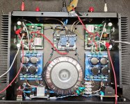
Try connecting the amp ground straight to the binding post output of the chassis. Only run the speaker out +ve through the speaker protection. You are probably getting a ground loop when you connect the amp -ve to a common ground on the speaker protection.
I don’t know how the speaker protection circuit is designed but it’s important that the DC protect sense circuit is galvanically isolated from the relay activation. This is usually done with an optoisolator. Without this, there will be ground loops and distortion.
There is a SSR speaker protect in my shop that works well and uses optoisolators.
Hello.
I have finally finished amplifier and I am simply astonished by the sound. Of coarse, things have to settle a bit, but sound is already amazing. For sure this amplifier deserve nice enclosure, which will be my next project 😉
I already have some special PSU which have two separate outputs: +- 55V (regulated) for input/VAS section and +-50V (unregulated) for putput stage. Do you think this PSU would be useful on this amplifier (thinking of removing R128/R129 resistors)?

You can check one more option - to connect a wire from PSU 1 ground to the other psu ground and then use the protection module with the input grounds and output grounds. Most of these kind of protection modules need the input/output ground sense on the board to get the relays working as per the design. As you are using a single transformer with multiple secondary and 2 independent psu boards it tends to get into the group loop as XRK suggested.Hi, I have problem with speaker protection in this amplifier. It have common ground and if i connect both speakers i get high distortions from the speakers. With only one (like on the picture) it works.
Any other solution than additional speaker protection board for other channel?
Excellent news! Glad you like the sound. It’s one of the best Class AB amps in my opinion.Hello.
I have finally finished amplifier and I am simply astonished by the sound. Of coarse, things have to settle a bit, but sound is already amazing. For sure this amplifier deserve nice enclosure, which will be my next project 😉
I already have some special PSU which have two separate outputs: +- 55V (regulated) for input/VAS section and +-50V (unregulated) for putput stage. Do you think this PSU would be useful on this amplifier (thinking of removing R128/R129 resistors)?
View attachment 1027554
I don’t know how well your dual voltage scheme will work. You are welcome to try but I don’t think it’s necessary. I would simulate first on LTSpice.
Hi Everyone,
Back to building, and have a question about attaching output wires to a 5 way speaker binding post.

Plans are to remove insulation on the crimp eyelet and solder output wire to the eyelet. I will then slip the eyelet over the stud and secure it to the stud washer with the lock washer and the 2 nuts. Eyelet/wire connection will be insulated with shrink tube.
Reason for this: soldering a wire on the tip end of the stud means that I would not be able to unscrew the nuts in case of problem with binding posts.
If I cannot do this, please let me know another method.
Thanks for the help,
MM
Back to building, and have a question about attaching output wires to a 5 way speaker binding post.
Plans are to remove insulation on the crimp eyelet and solder output wire to the eyelet. I will then slip the eyelet over the stud and secure it to the stud washer with the lock washer and the 2 nuts. Eyelet/wire connection will be insulated with shrink tube.
Reason for this: soldering a wire on the tip end of the stud means that I would not be able to unscrew the nuts in case of problem with binding posts.
If I cannot do this, please let me know another method.
Thanks for the help,
MM
That's how I would do it. Just curious, is there a reason your soldering the wire to the eyelet and not just crimping it? Either way should be fine. Just asking
@thirdicomplex Thanks for the reply. I have lot's of crimps in the build, just trying to eliminate possible loose wires where ever I can.
A proper crimp connection with crimp tool actually cold-welds the wire to the crimp ferrule and doesn’t make the wire solid with wicked up solder. That may reduce strain resistance. However, for an internal speaker binding post connection, soldering to the crimp connector is probably fine. Use 16ga high strand count silicone insulation “RC Drone” wire for the crucial PSU to amp and amp to binding post connects. This wire has superior amperage ratings vs standard wire. This can lower output impedance and improve bass authority.
Even better, use 12 ga variety. Similar to this. Can find on eBay or AliExpress.
https://www.ebay.com/itm/2343265236...Y9mcKZ3Rq-&var=&widget_ver=artemis&media=COPY
Even better, use 12 ga variety. Similar to this. Can find on eBay or AliExpress.
https://www.ebay.com/itm/2343265236...Y9mcKZ3Rq-&var=&widget_ver=artemis&media=COPY
Thanks for the info X, I have basic crimp pliers with the V or U shaped cup and the V shaped pin. One set of crimp pliers has 3 ranges for the guage of wire used, so may resort to crimping rather than soldering.
MM
MM
I am back to building/rebuilding my FH9HVX amp. I have decided to leave out the Fo-Felix CMC modules, as I have no room for them. I am also changing out the wire to silicone wire. I have attached a image of the IEC inlet and the SFP board wired to the primaries wired in parallel. Red wire is Line and Black wire is neutral from the IEC block to the SFP board. I am assuming that I can just parallel the primaries and hook up to the outlet of the SFP board as shown.
Thanks in advanced for the help, if I have wired incorrectly.

Thanks in advanced for the help, if I have wired incorrectly.
Good news is that after changing wires to RC silicon wire, which is so easy to work with, I powered up one channel and adjusted to 26mv bias and had 8 mv on the output. Powered up the 2nd channel and adjusted to 26mv and had 2.0 mv on the output. Powered on both channels, and the amp is settling in around the 26mv bias range. Will hook up instant off board and the Gen1 RTRSSR boards, and populate the rear panel with the inputs and outputs.
Bad news is that I tested positive for Covid. How is a mystery to me, I had no problems in Mexico, it was very safe there. I come back to the Mountains and isolation, and I pick it up. What gives with that. It seems to be like a flu or a bad cold.
One other good thing is that it keeps me at home, so I can spend time finishing my projects. 👍
MM
- Home
- Group Buys
- FH9HVX - Budget Conscious 100w Class AB for Lean Times