Vunce,
So I twisted the inputs together, soldered my power inlet and.....voila, no noise from the speaker.
Should my next plan be to connect the grounds of the other channel to the star ground and twist the inputs as before, power up and check? I will disable power to the first channel before powering 2nd channel, Correct?
MM
Hi Myles,
Great news! The twisted pair does wonders for reducing EMI pickup. And no alligator clips on ground connections, which need to be low impedance.

Great news! The twisted pair does wonders for reducing EMI pickup. And no alligator clips on ground connections, which need to be low impedance.
Thanks Guys,
I managed to find some time before golf to connect the second channel and power up. Another success with no noise from speaker.
It is time to work on my enclosure, to mount peripheral components. I have a question relating to grounds again:
In my diagram below, the SFP will be mounted to chassis, so should not need ground wire to star post (Correct?). The 2 emi filters will be mounted to an "non-metal enclosure" and the outputs of the emi filters attach to the terminal block and then to the transformers.

Question: I should not have to ground the emi filters, due to connection to the SFP.
Thanks for the help,
MM
I managed to find some time before golf to connect the second channel and power up. Another success with no noise from speaker.
It is time to work on my enclosure, to mount peripheral components. I have a question relating to grounds again:
In my diagram below, the SFP will be mounted to chassis, so should not need ground wire to star post (Correct?). The 2 emi filters will be mounted to an "non-metal enclosure" and the outputs of the emi filters attach to the terminal block and then to the transformers.
Question: I should not have to ground the emi filters, due to connection to the SFP.
Thanks for the help,
MM
Hi Myles,
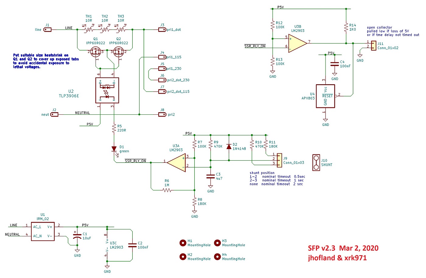
The SFP only deals with AC line and neutral return. There is no earth ground or protective ground connection on it. The standoffs are on isolated parts of the PCB. There is a ground for the remote control logic, but that’s not the same as a PE ground.
Why do you need external EMI filters? What are those filters? Usually the filters will be in same chassis as the PSU and metal case contains the EMI.
No PE shown in schematic:
Thanks for the reply X,
Look at this : GB Round #8 Fo-Felix AC filter (Destroyer X). This is on page 2 of the GB's.
threads. Supposed to filter noise from the mains before transformers.
MM
Look at this : GB Round #8 Fo-Felix AC filter (Destroyer X). This is on page 2 of the GB's.
threads. Supposed to filter noise from the mains before transformers.
MM
Your transformers are pretty hefty filters themselves. I suppose it doesn't hurt to have a common mode choke (CMC) as a filter - but that could also be done after the rectifier bridge.
So do you mean connecting the CMC between the PSU and the amp board ?. If so, with only Line and Neutral on the in/out of the CMC, how would I connect this?
MM
MM
Never mind - you would need either a balanced or two CMC’s. If the one on your FoFelix was made for single phase mains, that’s where you would use it.
Can i use 10V capacitor instead of 16V for C106? The 16V is not on stock from where i can buy. I use 2x42V DC power supply.
Hi X,
Thanks for the answer about the OV pad on the RTR SSR thread. I have one other question concerning mounting the Instant Off module.
I will be mounting 2 of these to the base of my metal chassis. Do I need to electrically insulate the vero board pcb from the chassis base with nylon washers?
Thanks for the help,
No, unless the screw touches some active circuit path. But if the holes are electrically isolated you are fine. You might be able to power two SSRs with just one of these boards. That’s what I do.
Thanks X,
I drilled 2 mounting holes away from the p2p circuitry, so should be good. I will be installing one module per channel. Lots of room between the amp boards. I will then mount the RTR SSR modules on the enclosure panel.
MM
I drilled 2 mounting holes away from the p2p circuitry, so should be good. I will be installing one module per channel. Lots of room between the amp boards. I will then mount the RTR SSR modules on the enclosure panel.
MM
Is there any modification needed to amplifier values, if using 35Vac transfomer secondaries (+-49Vdc)?
Is there any modification needed to amplifier values, if using 35Vac transfomer secondaries (+-49Vdc)?
No it will be fine as it is posted
It depends on how much power you plan on running continuously. Full power then size it like a Class A amp. If you like to run at say, 25w on average then use 0.67x efficiency factor for Class AB.
So about 1/3rd of power is dissipation or about 12-15w is round number. Assume 25C ambient and assume you don’t want heat sink more than about 55C. So that is 30C rise.
So there is your K/W rating for 25w continuous: 30C(K)/15w or 2K/W.
If you want to size it for say 50w continuous then 1K/W.
Or 100w continuous then 0.5K/W (like a big a class A amp).
- Home
- Group Buys
- FH9HVX - Budget Conscious 100w Class AB for Lean Times