Hi Myles,
Please draw a sketch of a block diagram of your grounding scheme, showing where things are connected to the chassis ground. The 0v analog GND (clean ground) should only touch the chassis ground and IEC ground (dirty ground) via a ground loop breaker (GLB). Usually the GLB is a 8ohm to 10ohm NTC or 10ohm resistor and some back to back diodes.
When you touch something like the chassis or heatsink and the hum is reduced, it means that your amp signal input or your main amp ground has a ground loop.
When I get ground loops, I first ground all my inputs and see if it is still there. If inputs grounded and hum still there, you have some sort of improperly grounded connection between your amp and PSU.
Then connect only one signal input RCA on one channel using a battery powered isolated source (your smartphone or digital audio player from 3.5mm to RCA adapter is perfect for this). If it plays on 1 channel without hum then you know it is a ground loop. The connect the 2nd RCA and if hum now starts then definitely you have a ground loop.
Instead of sanding away paint etc on heatsink, I sometimes connect a big thick 16ga copper ground wire with a crimp loop connector to a bold on the heatsink (sand paint off at the bolt if needed) and tie that ground to your chassis star ground hub.
Ground loops can be controlled if you make all ground and earth connections deliberately. That is, nothinng just happens to touch ground.
Also, make sure your input signal from the RCA jack does not traverse anywhere near the toridal transformer as that can induce hum.
Next thing is to take a clear picture of your amp layout - top view with IEC, trafo, PSU board, soft start board etc all in view.
Are your RCA connector jacks insulated or touching the chassis?
Thank you all for the help and especially X for the ground loop explanation. After reading and looking at this post, things may be a bit clearer.
Pete, On the one channel that I have connected, there is no hum/buzz. There is a minor thump buzz, but quickly goes away.
1883, Nothing nearby, can move wires with no change.
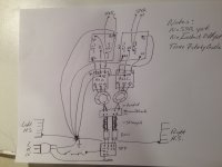
X and all, please see attached block diagram of how I hooked up everything before:
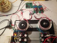
Here is a pic of the top part of wiring connections, without connections to SFP & EMI filters. Only shows connection to 1 channel.
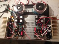
Here is a pic of the bottom part of wiring connections, again only 1 channel connected.
Here is a pic of the gnd post and area around the PS.
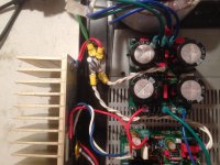
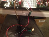
Here is a pic of the inputs and the wire connection to an rca connection. I just have it in my lap for the picture. Gnd goes to rca solder tab and In goes to the center pole on the rca connector. If I connect this and turn on power, I receive hum instantly.
X, I will have to look into building a GLB, if the SFP is not sufficient to handle the loops. I will also see what attachments I have around for hooking into my phone. I know I had one for my computer that had some rca ends, just have to find it.
Thanks,
Myles
Pete, On the one channel that I have connected, there is no hum/buzz. There is a minor thump buzz, but quickly goes away.
1883, Nothing nearby, can move wires with no change.
X and all, please see attached block diagram of how I hooked up everything before:

Here is a pic of the top part of wiring connections, without connections to SFP & EMI filters. Only shows connection to 1 channel.

Here is a pic of the bottom part of wiring connections, again only 1 channel connected.

Here is a pic of the gnd post and area around the PS.

Here is a pic of the inputs and the wire connection to an rca connection. I just have it in my lap for the picture. Gnd goes to rca solder tab and In goes to the center pole on the rca connector. If I connect this and turn on power, I receive hum instantly.

X, I will have to look into building a GLB, if the SFP is not sufficient to handle the loops. I will also see what attachments I have around for hooking into my phone. I know I had one for my computer that had some rca ends, just have to find it.
Thanks,
Myles
I cant get R151 from the BOM. Will be this ok?
https://eu.mouser.com/ProductDetail/Ametherm/SL15-60004?qs=VFU/nhgRIqAwKELlGcBi4w==
Or is ther anything better on stock from mouser?
https://eu.mouser.com/ProductDetail/Ametherm/SL15-60004?qs=VFU/nhgRIqAwKELlGcBi4w==
Or is ther anything better on stock from mouser?
Thanks for posting the details, Myles. We will all look at this and get back to you. I think Vunce is the expert here on this subject.
This is for a ground loop breaker. Something closer to 10ohms is what you want. A CL-60 works too:
https://www.mouser.com/ProductDetail/Amphenol-Advanced-Sensors/CL-60?qs=w3gjcs3NwciEQjXGFRAAAA==
Cheap 8ohm NTC 8D-20 from eBay is also good. No audio passes through this. It’s a resistor to ground to reduce hum.
https://www.mouser.com/ProductDetail/Amphenol-Advanced-Sensors/CL-60?qs=w3gjcs3NwciEQjXGFRAAAA==
Cheap 8ohm NTC 8D-20 from eBay is also good. No audio passes through this. It’s a resistor to ground to reduce hum.
Hi Myles,
When you touch something like the chassis or heatsink and the hum is reduced, it means that your amp signal input or your main amp ground has a ground loop.
When I get ground loops, I first ground all my inputs and see if it is still there. If inputs grounded and hum still there, you have some sort of improperly grounded connection between your amp and PSU.
Yes! Agree…always important to make sure the source of the input signal isn’t part of the issue. Ground both input returns (-) with alligator clip leads.
Then connect only one signal input RCA on one channel using a battery powered isolated source (your smartphone or digital audio player from 3.5mm to RCA adapter is perfect for this). If it plays on 1 channel without hum then you know it is a ground loop. The connect the 2nd RCA and if hum now starts then definitely you have a ground loop.
One amp build drove me crazy with hum like you are describing using all the same components prior to amp. Turns out my DAC had a grounding connection issue that hadn’t bothered the amps I had tried before but it showed up on the new build. If I used my cellphone’s audio out to two RCA inputs the hum was not there.
Cheers and good hunting,
Pete
Thanks guys, one question: When you say ground the inputs, do you mean short the inputs with a alligator clip attached to In & Gnd and check for hum . Not sure of the terminolgy " ground the inputs". Sorry newbie at work.
MM
MM
This is for a ground loop breaker. Something closer to 10ohms is what you want. A CL-60 works too:
https://www.mouser.com/ProductDetail/Amphenol-Advanced-Sensors/CL-60?qs=w3gjcs3NwciEQjXGFRAAAA==
Cheap 8ohm NTC 8D-20 from eBay is also good. No audio passes through this. It’s a resistor to ground to reduce hum.
The one from your link is to big for PCB. What about this one:
https://eu.mouser.com/ProductDetail/Ametherm/SL15-25003?qs=PVyXUKBeRH355wh4C6r6Dg==
Same series as from the BOM just 25 ohms.
I don’t know why you saying too big? The lead spacing of CL60 vs the Ametherm is within a mm (bend the legs a little if you have to) and the ohms rating when cold is what is important. 25ohms is too big. 8 ohms to 10ohms is ideal. I typically 8D-20’s which require some bending of the legs to fit perfectly.
The limiter from your link have 19.56mm and the one from BOM is 16mm.
This one is from BOM:
SL15 47003 Ametherm | Mouser Europe
Inrush Current Limiter 16mm 47ohms 3A
In your last post you recommend 8 ohms to 10ohms as ideal.
What am i missing?
This one is from BOM:
SL15 47003 Ametherm | Mouser Europe
Inrush Current Limiter 16mm 47ohms 3A
In your last post you recommend 8 ohms to 10ohms as ideal.
What am i missing?
I recommend 10ohms but your link is 47ohms - too high. The diameter of 16mm vs 19mm is irrelevant. The pin spacing is about the same so look for an NTC with circa 8mm pin spacing and circa 10ohms.
Kokanee: see the picture. You’re only grounding the (-) or signal return parts of the RCA inputs to the earth ground (star ground). You can connect both of them at the same time.
Pete
Pete
Thanks guys, one question: When you say ground the inputs, do you mean short the inputs with a alligator clip attached to In & Gnd and check for hum . Not sure of the terminolgy " ground the inputs". Sorry newbie at work.
MM
Attachments
I recommend 10ohms but your link is 47ohms - too high. The diameter of 16mm vs 19mm is irrelevant. The pin spacing is about the same so look for an NTC with circa 8mm pin spacing and circa 10ohms.
Ok, thank you for clarification.
So this will be ok?
https://eu.mouser.com/ProductDetail/Ametherm/SL15-10006?qs=PVyXUKBeRH0i1CpIjjm51Q==
Maybe it would be good to update the BOM with right value.
Thanks Pete,
So what your saying to make sure I have this right: " I should have a wire (or alligator clip in my case) connecting the signal return to my star ground". Correct?
I thought that all analog grounds need to connect to a clean ground rather than the power star ground.?
Thanks for all the help,
Myles
So what your saying to make sure I have this right: " I should have a wire (or alligator clip in my case) connecting the signal return to my star ground". Correct?
I thought that all analog grounds need to connect to a clean ground rather than the power star ground.?
Thanks for all the help,
Myles
Myles, not knowing what your exact setup looks like (I tried looking at your picture), yes start with that connection. If that either makes it worse or nothing improves then ground to your PS general grounding connection (which may go to earth ground as well).
Is there a general build guide for this amp?
Pete
Is there a general build guide for this amp?
Pete
Thanks Pete,
So what your saying to make sure I have this right: " I should have a wire (or alligator clip in my case) connecting the signal return to my star ground". Correct?
I thought that all analog grounds need to connect to a clean ground rather than the power star ground.?
Thanks for all the help,
Myles
Hi Myles,
I’m trying to get a grasp on your current FH9HVX setup. Lets start from the beginning.
Both the amplifier boards and the All Cee’s PS boards have GLB’s built-in, no need to use another GLB externally.
Earth gnd from the AC inlet module attaches to a single point on the chassis(the bolt in your pic). If your heatsinks are attached to the metal chassis they should make continuous connection to earth gnd and should not need separate gnd wires to the “star” bolt. (check heatsink gnd continuity with your DMM). Connect your amp board PE and All Cee’s PE (GLB’s) to the star bolt. Which it looks like you did this already.
Never connect your sensitive signal gnd from input rca tab to dirty chassis gnd!! That will defeat the purpose of the GLB’s by bypassing them straight to chassis gnd. Alligator clips on the rca socket (signal/gnd tab) is not a good connection and could introduce all sorts of noise problems.
Also, you are building a dual mono amplifier, you don’t want to connect your signal input grounds together, they will not be separate anymore defeating the dual mono set up.
Try this, Remove the alligator clips and rca socket from the amplifier. Tie the red and white wires together, this will “short” your signal input. Then power up and check for hum/noise.
Hi Vunce, thanks for the help. I have been following the pic below as a guide for grounding and connections, and adapting to the components I am using.
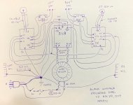
If it is better to attach heatsink ground to the chassis, I can easily do this
You are correct with the PE's from PSU & Amp attaching to the star ground post.
I am going to hard connect my inlet power live and neutral connections and I will also tie the input wires together and then power up. Will keep you informed in the next couple of days, as I am playing in our golf club championship on Wed & Thurs.
MM
- Home
- Group Buys
- FH9HVX - Budget Conscious 100w Class AB for Lean Times
