Hi Legis,
Your SSR’s were repaired today. I had to replace the exploded voltage regulators (one of which left a crater in the PCB beneath it - impressive) and the comparators on both boards. It’s working fine now and shipping out tomorrow. Hopefully you will have it by Monday. Looking forward to seeing your new FH9HVX amp.
Your SSR’s were repaired today. I had to replace the exploded voltage regulators (one of which left a crater in the PCB beneath it - impressive) and the comparators on both boards. It’s working fine now and shipping out tomorrow. Hopefully you will have it by Monday. Looking forward to seeing your new FH9HVX amp.
FrancoisG,
Just to let you know that I'm not ignoring your post. I was going to wait until I get my now repaired RTR SSR boards back from X before I post some pics.
Thanks for remembering and sorry to hear about the unexpected fireworks. No hurry with the photos. Get it back together and then take pics if you like. Good luck.
Hi X, Vunce, other builders
I thought I had everything good on the problem channel. All the lights were lt and I was setting the bias and watching the Vout. I went to move my heatsink about 1 inch and that when the smoke began. As far as I know, nothing moved. Shut down and investigated.
Found:
1. N & P MFets are toast. I have one pair of N&P Mfets left from test #1, so I measured them, and they measured O.L or in the Mohm range, so should be good to use.
2. Checked all resistors and compared to my good channel - looks good - except R144 the Dale CFP2 10 ohm 2 W resistor on both amp boards measures at 0.2 ohms. I removed from the bad channel and it measures 10.2 ohms on my LCR meter. Any ideas on why the difference when soldered on the amp board?
3. My Mfets have the wire soldered on the legs, so I will use them as is without the helper boards.
4. I checked my PS and it is operating as It should.
5. X, you asked me once if I had continuity between the Drain and my heatsink ground. I used my DMM and checked both channels. I put a probe on the Drain and one on the bolt on the heatsink with wire attached to ground. There was no noise (beep) from the DMM. I also put the probe on the ground block and had same result. Is this correct not to have continuity?
6. I will do some more investigating, and try my last pair of MFets after investigation is over. If this does not work, I think I may try to populate a new amp board.
If I can get some help with Q2 & Q5 above, I will be grateful.
Thanks,
MM
Hi Myles,
So sorry to hear this. Wow, it seems you have a pathological case here.
Q.2, if you look at the schematic, the R144 is part of the output Thiele network and is in parallel with a low impedance inductor. Hence you cannot measure its value in place. So when removed it measures correcty.
Q.5, the drain and heatsink should not have continuity. So that is good what you measure.
So why would MOSFETs fry if they are working well one second and then the next get smoked? That would indicate that either you are running into oscillations or thermal runaway. Both events can destroy the MOSFETs in about 1 to 2 seconds.
Oscillation should not be happening if you have the correct compensation capacitors in place, and you have the Thiele network (4.7R and inductor in parallel) and the Zobel network in place (that is the 100nF and 4.7R resistor to GND at the output).
So it suggests you may have thermal runaway - and thus might be caused by a bad Vbe temperature sensor transistor. The BD139 that sits on top of the MOSFET may not be telling the amp to slow down its bias curent when it gets hot. Try changing the BD139 to a fresh transistor. Also, mount it on the MOSFET that seems to get hot first. I generally mount it on the N-channel, but maybe the P-channel might be better.
You can tell if the amp had thermal runaway by looking at the backside of the dead MOSFETs. Does it look like solder is oozing out of the metal to epoxy interface? Oscillation will look more like the MOSEFT bulges and wants to explode vs just melting.
Thermal runaway can also be caused by not tightening the heatsink mounting bolts securely enough and hence, heat is not removed effectively. So when you went to move your heatsink a little, it was enough to not let the MOSFET cool sufficiently and thermal meltdown occured within seconds. Try to screw the MOSFETs down with a good ceramic insulator pad and paste. If not use silicone spacer but screw it down securely.
Nice work. Legis! Glad the amp is working out for you.
We will all have to help Myles get his up and running.
We will all have to help Myles get his up and running.
Thanks X and Jim for your input. I will have a look at what you mentioned and get back to you over the weekend.
This talk about the inductor reminded me, that I severed some of the pad around the lugs of the inductor when soldering. I thought I got enough of a solder bridge to make it work, but maybe not.
Can you measure the inductor in static condition from the bottom side or do have to have power to it?
I have some magnet wire, so could wind up an air coil if needed after checking all the other points mentioned.
MM
MM,
I don't have a dedicated LC meter but I would not recommend trying to measure a component's value under power or you'll be swapping out the fuses in your meter!
I don't have a dedicated LC meter but I would not recommend trying to measure a component's value under power or you'll be swapping out the fuses in your meter!
The inductor is not the issue. It will run fine 99% of the time without the Thiele network inductor + resistor in parallel - as was the case with the Apex FH9 XRK mod amp. It’s there to ensure stability when driving certain capacitive loads that might cause oscillation.
The main things to check why yours is not running would be (1) sufficient heatsink thermal contact, (2) properly operating Vbe multiplier (BD139) temperature sensor, (3) gross error in component value (resistor) or bad small signal transistors.
The way to debug is to put in some safety resistors (10w 10ohm) one each between the PSU and the amp. Turn it on and see if you can set bias current at something low like 20mA. It should be able to operate there if the parts are all working and if not, take a DMM and measure the voltages at all the pins of each active and redline the schematic, take a photo of your hand redlined schematic that shows voltages at each pin of each transistor. This is a complete diagnostic and tells all. We can isolate the problem instantly from this full diagnostic. It’s like an ER doctor asking for complete blood survey, X-rays, and CAT scans for a patient with unknown ailment.
If you continue to get problems maybe send the board to me and I’ll check it out for you. It really is a simple amp to get running - in my experience.
Last edited:
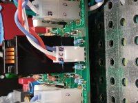
Thanks for post X, makes perfect sense. I have soldered back in place R144. The Vbe temp sensor is brand new and have tested it, shows as NPN.
I have not applied thermal grease to the mica pad/heatsink interface or the Mfet/mica pad interface. I thought I would wait until I had a successful power up. Should be OK?
I have checked all the resistors, diodes, have all components for the Thiele and Zobel networks correct.
I will be using a 10W 12 ohm set of resistors between the PS and amp.
I have attached some pics of the Mfets, and they look good, no melting, bulging, just blown.
Will power up carefully, once I give my mind a rest.
MM
You need to use thermal paste always when powering up. Unless you are using silicone pads, no paste needed but with either mica or ceramic, they won’t work without the paste as the tiny voids makes thermal transfer very poor. So all this time you have been powering up without thermal paste? Please use the thermal paste before the next test.
Thanks X,
I guess I got lucky with the channel that tested good. So I will put some thermal paste on the mica/ceramic pad and attach it to the heatsink. I will make sure I snug them down before slowly powering up.
A couple of trivial questions:
Do I also use thermal paste on back of Mfets?
My Mfet clamping bolts threads completely through the heatsink. I am able to tighten the Mfets without having a nut on the bolt, but I am afraid it may loosen. Do I need a nylon shoulder washer in front of the nut and lock washer?
Thanks for the help, Sunday will be test day.
MM
Hi Myles,
Thermal paste between all contact surfaces, especially the back of the MOSFET. If your bolt is threaded onto the heatsink no nut is needed. If it’s a loose hole then a nut and lock washer. Don’t over tighten as that can crack the MOSFET. I generally use just an M3 bolt into threaded aluminum heatsink with a washer made from a 5 cent nickel coin drilled out as large diameter (“fender”) washers are hard to find.
Thermal paste between all contact surfaces, especially the back of the MOSFET. If your bolt is threaded onto the heatsink no nut is needed. If it’s a loose hole then a nut and lock washer. Don’t over tighten as that can crack the MOSFET. I generally use just an M3 bolt into threaded aluminum heatsink with a washer made from a 5 cent nickel coin drilled out as large diameter (“fender”) washers are hard to find.
Hi X,
Powered up amp with al lights lit and no smoke. That is good. The following is what I recorded:
At 0V from the Variac, Bias was 0.0 mV. , Output was -52.4 mV, Bias adjustment did nothing.
At 28VAC from Variac, Bias was -90mV, Output was -7.5mV, again bias adjustment changed nothing.
I am open to ideas. Could it be the trim pot that is bad?
MM
Hi Myles,
Where are you measuring the bias current voltage across? I don’t understand why 0v at the variac would produce anything?
You want to measure voltage across one of the 0.22R KOA resistors. That voltage should change with the trimpot.
Where are you measuring the bias current voltage across? I don’t understand why 0v at the variac would produce anything?
You want to measure voltage across one of the 0.22R KOA resistors. That voltage should change with the trimpot.
Hi X,
I am measuring at the red and black test points, just in front of the 0.22R resistors.
Is it common to have negative values for bias and output?
After the test, I was testing the Mfets, and 2 legs fell off the BD139 where it was mounted on the N channel MFet. This part may have been defective while testing, so I will replace and test again.
Will post results after test.
MM
If your Bd139 had dodgy legs - that would explain why the bias current could not be adjusted, and possibly why your amp was not working earlier.
The positive and negative bias current depends on which resistor - but positive reading will result when current flows from positive to negative or from ground to negative rail with positive lead on the upper or higher voltage. The DC offset can go either way but should be under 20mV or less. Even 50mV is not a problem but I have found this amp to be very close to +/-5mV.
I suspect everything will work just fine once you replace the BD139 Vbe multiplier (temperature sensor).
- Home
- Group Buys
- FH9HVX - Budget Conscious 100w Class AB for Lean Times