Congratulations! 
Thanks btw, your explorations (and documentation) will be useful when I get to that point one of these days.

Thanks btw, your explorations (and documentation) will be useful when I get to that point one of these days.
Thanks, guys! I ran it for a couple of hours in my basement workshop today & the heatsinks didn't even get lukewarm. Before I test it in my living room though, I'm going to tidy up all the flying spaghetti wires by routing them on the floor of the chassis.
I'm pleased to report that there was no discenable hiss or ground loops and dc offset (inputs shorted) was less than 3mv on both channels without my fried ssr boardsand there was no turn off thump!
Thank you all for your help on this one!
Jim
I'm pleased to report that there was no discenable hiss or ground loops and dc offset (inputs shorted) was less than 3mv on both channels without my fried ssr boardsand there was no turn off thump!
Thank you all for your help on this one!
Jim
Hi Legis,
Great news:
The 3mV offset is outstanding. No hiss and no ground loop hum is awesome and the sign of a great well executed build. Congratulations!
I am sure you are going to enjoy this amp. It’s got a nice muscular sound that is very non fatiguing and foot-tapping good!
Great news:
I'm pleased to report that there was no discenable hiss or ground loops and dc offset (inputs shorted) was less than 3mv on both channels without my fried ssr boardsand there was no turn off thump!
The 3mV offset is outstanding. No hiss and no ground loop hum is awesome and the sign of a great well executed build. Congratulations!
I am sure you are going to enjoy this amp. It’s got a nice muscular sound that is very non fatiguing and foot-tapping good!
Congrats to Legis31 on his successful build. I am ready for the 2nd attempt of power up.
I have checked all solder connections and reflowed some bad ones.
I have checked and measured resistors, caps, transistors, and should be good to go.
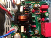
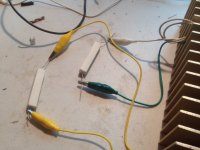
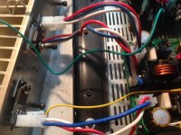
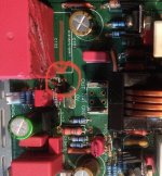
I have attached 3 pics: mfets on HS, mfets on boards, and 10W10R hook up with clips coming from the PS to the resistor and from resistor to the amp board.
Please have a look at the pics, and let me know if anything looks wrong.
Thanks,
MM


Hi X, Vunce, other builders,
Powered up for the 2nd time, and my bias readings and voltage out were all -DC readings. The bias before I shut it down (70VAC) was -380mV DC and Vout was 0.055V. The 10W 10ohm resistors between the PS and amp were hot. The trim resistor had no effect on the readings.
Changed out the resistors and powered up again. This time at 70V AC, I had Vout at -0.044V and bias was 266mV. The trim resistor seems to slip at the end of a turn, and has no effect clock wise or CCW. I must have got to aggressive with turning the screw.
I will change out the trim resistor. Any idea as to why I would be getting negative bias readings?
Thanks,
MM
I think I made a mistake in post #868:
I think my GDS is Blue White Red on the helper board, which should match the GDS on the amp pcb. Could some one verify this for me from the pictures?
Thanks,
MM
I think my GDS is Blue White Red on the helper board, which should match the GDS on the amp pcb. Could some one verify this for me from the pictures?
Thanks,
MM
Hi Myles,
From what I can see, your photos show GDS on the main PCB as Blue / White / Red
and on the helper board you have GDS as Blue / White / Red. So that looks good.
Your temp sensor Vbe multiplier is White / Blue / Red and matches ECB on the actual unit.
So all this looks good.
Are you sure you have the correct KSA1381/KSC3503 installed in the correct places?
Finally, do you have the correct P-channel and N-channel MOSFETs in the correct places? P chan on left (IRF9240 etc) and N chan on right (IRFP240 etc).
Is LED H111 correctly oriented, does the LED light up? Cathode (flat) fces the 0V spade terminal.
Last edited:
Thanks guys for the input. My one channel powered up without any problem. I will check everything mentioned, and then double check on the channel that is not operating correctly. Will let you know.
Thanks,
MM
Thanks,
MM
Hi Myles,
From what I can see, your photos show GDS on the main PCB as Blue / White / Red
and on the helper board you have GDS as Blue / White / Red. So that looks good.
Your temp sensor Vbe multiplier is White / Blue / Red and matches ECB on the actual unit.
Is LED H111 correctly oriented, does the LED light up? Cathode (flat) fces the 0V spade terminal.
X,
Don't you mean the LED anode faces the spade terminal?
future build pics
FrancoisG,
Just to let you know that I'm not ignoring your post. I was going to wait until I get my now repaired RTR SSR boards back from X before I post some pics. I had utterly fried both boards when I got the voltage polarity reversed and suffered my first flash-bang disaster! I also wanted to revamp the lines from the PSU from flying spaghetti wires to a more aesthetically pleasing routing of said wires along the floor of the chassis which I finished up a couple of days ago. I can post a couple of pics later tonight but technically what you'll see is incomplete until I reinstall and test them and I promise to use my DBT this time when I do! Stay tuned....film at 11!
Please post a few pics of you build. Enjoy.
FrancoisG,
Just to let you know that I'm not ignoring your post. I was going to wait until I get my now repaired RTR SSR boards back from X before I post some pics. I had utterly fried both boards when I got the voltage polarity reversed and suffered my first flash-bang disaster! I also wanted to revamp the lines from the PSU from flying spaghetti wires to a more aesthetically pleasing routing of said wires along the floor of the chassis which I finished up a couple of days ago. I can post a couple of pics later tonight but technically what you'll see is incomplete until I reinstall and test them and I promise to use my DBT this time when I do! Stay tuned....film at 11!
- Home
- Group Buys
- FH9HVX - Budget Conscious 100w Class AB for Lean Times
