Hello Forum Members,
A brief update on the hum problem in my FH9HVX. Thank you to X and Anand for your advice, I believe X may have helped me out here more than he realizes. As he pointed out the SFP board that I removed had no ground pin. I mistakenly thought this was the case when disassembling the amp. Looking at old pics of my build, a ground wire ran directly adjacent to the SFP board. Because of this, when I reassembled the amp I removed the ground wire that I thought went to the board.
I will run the shorted input test first. It's too early to know for sure, it does seem likely though, that I removed a necessary ground wire to some component. It wouldn't surprise me if this was a self-inflicted issue. I will keep everyone updated. Thank you for your advice.

Hello,
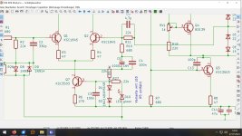
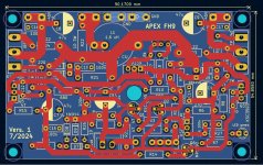
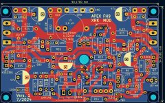
because i have the time and desire, i made a new PCB for this wonderful amp. Instead of R5 to the Capacitor, i choose the variation with R27/LED. Dont know if the board will work until yet, i have to test it out.
No smd components are needed and the biggest change...values on the PCB. Enough space for a big inductor. The board get a groundplane for GND. The board length is a little bit shorter. 90mm instead of 100 mm. The height is about 55 mm. That makes the PCB a bit cheaper if ordering PCB's.
I have attached two pictures.
Best regards
Peter
Attachments


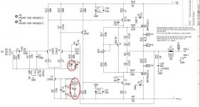
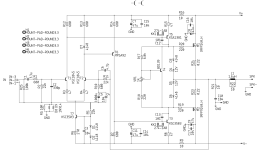
Can you show the schematic of what you did? If you want an LED indicator, replace the two 1N4148 diodes (0.6v drop each) with a single LED with 1.2v drop. I am afraid what you did was add a voltage drop with green LED to the base voltage control of the KSC3503 and that will cause a DC setpoint variation that is now not a nominal value.

Hi,
many thanks. I have the two diodes in. No problem, my mistake. I will delete the two diodes. A few minutes... )
Another Question....with the LED the capacitor is to change too ? From 1000 µf to 220 µF ?
Greetings
Peter
many thanks. I have the two diodes in. No problem, my mistake. I will delete the two diodes. A few minutes... )
Another Question....with the LED the capacitor is to change too ? From 1000 µf to 220 µF ?
Greetings
Peter
Attachments

Hello,
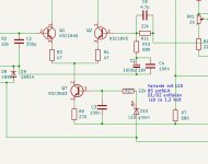
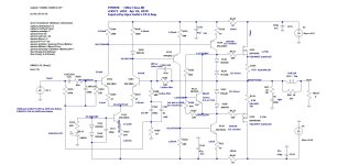
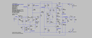
I was trying to mod FH9 XRK to accomodate locally available parts (notably the 2SD669/2SB649), it just needed adjusting of resistor values in the VBE multiplier circuit. I have added one red led tied to the emitter of Q9 VBE trannie as an aid for thermal tracking. Simulation works fine but why am I getting negative voltages all over?
I was trying to mod FH9 XRK to accomodate locally available parts (notably the 2SD669/2SB649), it just needed adjusting of resistor values in the VBE multiplier circuit. I have added one red led tied to the emitter of Q9 VBE trannie as an aid for thermal tracking. Simulation works fine but why am I getting negative voltages all over?
Attachments

Last edited:
Hi Peter,
R9 (22k) in my schematic should be fine as it was tied to the power ground. I always separate power sources ground to the feedback ground (via 10r groundlift per your schematic).
Regards,
Albert
R9 (22k) in my schematic should be fine as it was tied to the power ground. I always separate power sources ground to the feedback ground (via 10r groundlift per your schematic).
Regards,
Albert
HiHi,
are you sure R9 is grounded ? In my first schematic R9 is 22k and connected to the feedback...dont know if that could be the reason...
Greets
Peter
his R9 is in the original schematic R5. so its okay i guess.
Hi AlbertHello,
I was trying to mod FH9 XRK to accomodate locally available parts (notably the 2SD669/2SB649), it just needed adjusting of resistor values in the VBE multiplier circuit. I have added one red led tied to the emitter of Q9 VBE trannie as an aid for thermal tracking. Simulation works fine but why am I getting negative voltages all over?
is see negativ currents but i dont know why.
Thank you guys for your feedback, it was fine now. I snatched 😄 FH9HVX .asc file and edited its entries to match with my schematic diagram.
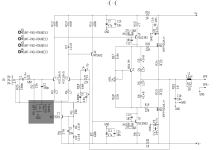
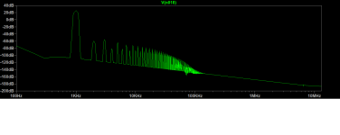
I just do not know if I still could name my mod as 'FH9 XRK mod' as I have adapted TMC in my schematic. Reason was, in order to come up with bode plot figures according to my preference. If time (and resources 🙂) permit, i will create the PCB.
Shown attached here was bode plot using Tian method. 1khz and 20khz FFT window at estimated full power.
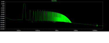
Attachments
Last edited:
CDIL is offering 2SC2240 or 2SA970. https://www.reichelt.de/de/de/index.html?ACTION=446&LA=3&nbc=1&q=2sa970
I havent bought until yet, because i have old toshiba in stock.
Also SB649 and SD669 manufactored by iscsemi and utc are to find at reichelt
https://www.reichelt.de/index.html?ACTION=446&LA=3&nbc=1&q=2sb649a
Dont know about hFE matching. The old Toshiba 2SC2240/A970 had a good series consistency.
Greets
Peter
- Home
- Amplifiers
- Solid State
- FH9 XRK mod