Happy new YEAR to all members and their families!!!
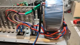
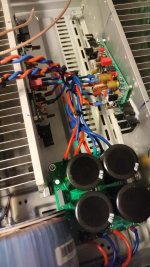
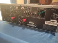
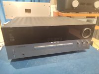
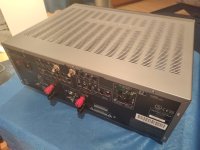
here are the final pics of my amp -FH9 XRK mod in AVR housing.
Amp is running and sound is nice...i will give it some days to compare to FX8 but the sound is promising.
what i learnt from this journey is that the housing might be cheap but you need 2 heat sink so you need another housing too. they were about 40 euros as defect sold.
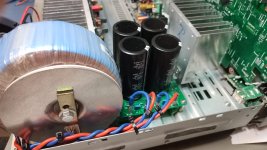
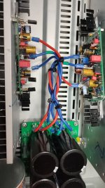
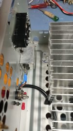
and that is what you get :
chris
here are the final pics of my amp -FH9 XRK mod in AVR housing.
Amp is running and sound is nice...i will give it some days to compare to FX8 but the sound is promising.
what i learnt from this journey is that the housing might be cheap but you need 2 heat sink so you need another housing too. they were about 40 euros as defect sold.
and that is what you get :
- - not the optimal heat sinks.
- - less room because the heat sink are in the housing 🙄
🤣 - + an EI- transformer with 35 -to 45 VAC and the VA of that is unknown.
but if you look at the power consumption plate in the back panel you can roughly estimate- e.g. 250WATT consumption---> is about 300VA.
correct? or? - - more or less useless caps...to old and 6800µF
- + i have got exactly the coils which i need - 1,5µH (pioneer AVR)
- + MPC725 Emitter 5WATT resistors.
- - you have to do a lot of drilling for holes and adaption for your amps
- + costs are about 40 euros
chris
Attachments
-
 FH9 XRK mod_pre installation_15.jpeg208.7 KB · Views: 130
 -
 FH9 XRK mod_pre installation_16.jpeg218.2 KB · Views: 134
 -
 FH9 XRK mod_pre installation_17.jpeg234 KB · Views: 134
 -
 FH9 XRK mod_pre installation_18.jpeg187 KB · Views: 131
 -
 FH9 XRK mod_pre installation_19.jpeg241.2 KB · Views: 133
 -
 FH9 XRK mod_pre installation_20.jpeg180 KB · Views: 144
 -
 FH9 XRK mod_pre installation_21.jpeg147.9 KB · Views: 129
 -
 FH9 XRK mod_pre installation_22.jpeg228 KB · Views: 121

Nice work upcycling old junk!
I love this approach to cost cutting.
I have had similar difficulty reusing old av receiver chassis.
Holes were you don't want them.
Stamped features in the way.
Back panel a holey mess.
I've taken to keeping the lid and using a cheap Chinese sheet metal bender to re-engineer the bottom and back.
Its a bit of work but it makes the end result much nicer.
Heres one i did recently out of sn old pioneer receiver and some salvaged steel from an old dishwasher.


More work to then cut/drill out the features you want. But at least you only have the features you want.
I love this approach to cost cutting.
I have had similar difficulty reusing old av receiver chassis.
Holes were you don't want them.
Stamped features in the way.
Back panel a holey mess.
I've taken to keeping the lid and using a cheap Chinese sheet metal bender to re-engineer the bottom and back.
Its a bit of work but it makes the end result much nicer.
Heres one i did recently out of sn old pioneer receiver and some salvaged steel from an old dishwasher.
More work to then cut/drill out the features you want. But at least you only have the features you want.
Neat, I never thought of repurposing old sheet metal panels from kitchen appliances! 🙂
Cutting holes in those is hard work! Steel sheets really like stamped punches. Not drills. But you get the 1970/1980’s OEM look though.
Btw, different subject, I ran across a CoilCraft flat copper inductor rated for 100A. These are flat inductance of 1.5uH over 100A and up to tens of MHz. Nice part for Thiele network on the output.


Just a cool looking part and quite a bit smaller than the one on FH9HVX. These are $5ea.
Cutting holes in those is hard work! Steel sheets really like stamped punches. Not drills. But you get the 1970/1980’s OEM look though.
Btw, different subject, I ran across a CoilCraft flat copper inductor rated for 100A. These are flat inductance of 1.5uH over 100A and up to tens of MHz. Nice part for Thiele network on the output.
Just a cool looking part and quite a bit smaller than the one on FH9HVX. These are $5ea.
It's not too bad.Neat, I never thought of repurposing old sheet metal panels from kitchen appliances! 🙂
Cutting holes in those is hard work! Steel sheets really like stamped punches. Not drills. But you get the 1970/1980’s OEM look though.
A bit of patience and a step drill bit.

I use a cordless jigsaw with a metal cutting blade for things like IEC power sockets.

I've come to love rivet nuts for holding things together.
I also discovered one can make a dimple die out of a bolt, washers, a socket and an impact wrench.

Keep the costs down and she who must be obeyed happy!
Today i tried to adjust the biassetting of my bigger amp. I can adjust the voltage, but DC offset is rising. On one channel i got 20,9 mV, the other channel has awfully 192 mV. Any idea what could be the reason ? What can i do to check the reason....
I have matched the KSC1845 to 431 hfe. The other transistors i have tested before i soldered in.
I have matched the KSC1845 to 431 hfe. The other transistors i have tested before i soldered in.
192mV is kind of high. Measure voltages at all nodes of actives and mark up schematics as redlines and post here to help us debug. Or you can also post over in my XRK Forum.
https://www.diyaudio.com/community/forums/xrk-audio.170/
https://www.diyaudio.com/community/forums/xrk-audio.170/
Ok, thank you. Because its to difficult to measure in the case i will take the board out. give me one or two days...
Thanks
Peter
Thanks
Peter
Today, over the whole day, i tried to find a mistake on the board...nothing to find. I changed all transistors, z diodes, measured the connections on the pcb, looked and measured the right values of the resistors, changed the 1000 µf/16 V capacitor...nothing to find.
The transistors i took out all ok. I have measured with two different meters.
But it went worse. Now, on this board, it is no more possible to make a bias adjusting. The bias is remaning at 174 mv, the lowest adjustment i can make.
So i soldered another board. On this board the bias is moving up and down.... not funny....😡
I wonder why this all happens.
I have to rest my eyes now...tomorrow perhaps is a better day...
I reorderd 5 new pcbs . I do not give up
oh Peter, sorry to here that.
did you check the DC with shorted input after the input stage (IPS), then step to the right side, step by step.
yes make a pause...then try it.
did you check the DC with shorted input after the input stage (IPS), then step to the right side, step by step.
yes make a pause...then try it.
Small success... the two boards are working. Unfortunaly the two boards are oscillating a little bit. If i adjust the bias to 12mV for example the voltage not remains at this point.
I get a voltage between 11,9, 12,2 and 12.8 mV. For testing i soldered a 3,3k instead of 6,8 k in. No success....i will change back. I wonder why this two boards do so. I have measured every transistor...all ok. I found a mistake i made. Instead of 680 R i soldered 6,8 k in. That was r12 on one of the boards. This was the reason i could not adjust the bias and it was to high.This happend on the newer board i built.
I found out that the oscilating voltage is reaching the BD139 on the two boards. The pot i have changed. No improvement. Is it possible that the effect has something to do with the negative feedback ?
Any idea i can do ?
Hi Peter
good!...that you found the error. !!
about DC offset- yes i have this too. i reported this in a post above. it toggles a bit around about 10mV. if i understand right that is the Vbe multiplier Transistor = T4.
the thermal Controlling (regulation) circuit needs a bit time for that.
i read years ago that a To92 Transistor is quicker as Vbe thermal controller transistor...but....the power is not for handling our big transistors because of current capability.
chris
Hi Chris,
i will change from my testing heatsink to the bigger heatsink tomorrow. I will give more time to the thermal circuit. Perhaps the testing heatsink is to small and is heatin up to fast. We will see. If i remember right, this problem did not occure in my little amp. There was no oscillation in that way.
**** happens.... 🙂
Could be lack of thermal mass and the temp compensation doesn’t have enough damping so bias oscillates. Be careful you don’t burn the outputs. They can go poof if thermal runaway due to insufficient heatsink or no heatsink. Takes 1 second.
I was careful. The testing heatsink is not big, but it takes over 15 minutes to get a temperature of a little bit more than 30 degrees. Only once it took time to measure some points. I wanted to compare the voltage from the working board to my non working pcb...
Tomorrow i switch to the bigger heatsink...i hope everything is stable...
Greets
Peter
Tomorrow i switch to the bigger heatsink...i hope everything is stable...
Greets
Peter
i know from my Class A 20W/8R First Watt amps that it is for checking the temperature of heat sink, MOSFET etc. and stabilizing the final bias setup necessary to check finally at 1 hour. all 10min - 15min check in between.
if you cannot touch the heat sink longer than 3 seconds than its realy HOT >55°C.
check MOSFET temp
if you cannot touch the heat sink longer than 3 seconds than its realy HOT >55°C.
check MOSFET temp
Hi again,
busy with other things...
Sound compare FX8 bimo mod vs FH9 xrk mod:
Both amps have the same bias 750mA, same power supply Sedlbauer 24V 300VA, Cap bank Q17 with 2x33mF per rail.
so they are similar 😉. Output is therefore the same 31,5V per rail.
after more sound session over my LS i can give following feedback.
both amps are very nice sounding and neutral amps with clear and neutral amps.
FX8:
pros:
cons:
FH9:
pros:
cons:
this impression are done over all kinds of music.
kr
chris
busy with other things...
Sound compare FX8 bimo mod vs FH9 xrk mod:
Both amps have the same bias 750mA, same power supply Sedlbauer 24V 300VA, Cap bank Q17 with 2x33mF per rail.
so they are similar 😉. Output is therefore the same 31,5V per rail.
after more sound session over my LS i can give following feedback.
both amps are very nice sounding and neutral amps with clear and neutral amps.
FX8:
pros:
- sound stage is deeper, 1m behind the LS
- very linear over all frequencies with little bit more preference in mids
- lay back sound, very relaxed, and sounds "warm"
- contoure of instruments and humans are more defined
cons:
- at max power feels more stressed
- bass could be a bit more and more controlled
FH9:
pros:
- sound stage not so deep, stage is in the front line, a bit wider left/right
- very airy highs...give you the feeling that the high go up up
- very controlled and massive, controlled bass
- easy to get loud with this amp
cons:
- contoure are not so exact
- highs are more "white" and not golden...sounds strange i know😉
this impression are done over all kinds of music.
kr
chris
both amps are very nice sounding and neutral amps with clear and neutral amps. 🤣 🤣 🤣
correction:
both amps are very nice sounding amps, very neutral and clear...no noise
correction:
both amps are very nice sounding amps, very neutral and clear...no noise
I would also say the bass authority was what I noticed being significantly different and the lower strain at higher volume is due to less distortion. I am not sure what is meant by contour? Frequency response profile? It should be flat 10Hz to 100kHz.
with contour i mean that the "holographic" is better...you here more detailed a gitarre or a drum...you can better imagine that you "see" this instrument...or voice.
- Home
- Amplifiers
- Solid State
- FH9 XRK mod