Hi borys, i have used hitachi k413 / j118 can i use them? Any value change with this hitachi fet?
Thanks
Thanks
On my darlington amp voltage drop is only 2,5V.You didnt get my point. On the collector you will have let me say 35V per rail but amplifier is a bastard and is stilling aprox 6V from it - so at emiter You will have approx 28V max amplitude with clipping!!
@shaan
Ofset 10mV with one npn darlington and one classic pnp 🙂
I don't have PNP's more 🙂
With all parts same,ofset only can be better.
Last edited:
Hi borys, i have used hitachi k413 / j118 can i use them? Any value change with this hitachi fet?
Thanks
It looks like they have high Ugs (similar to IRFP transistors) You may have to change biasing circuit to get around 6V between o/p transistors gates. If you solder back together the amp there will be only a matter of changing one or two resistors to get them biassed properly.
What you say for this?
4 x 4cm 😉
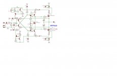
One error in it: The lower VAS's collector is connected to the lowest diode's negative leg. It should go to the positive leg and also to the base of the lower power transistor.
Otherwise very impressive.

Hi Idefixes!I think so...
Marc
Instead of transistors 2sc2922/2sa1216 can I put MJ15003/MJ15004 or required some changes to the schematics?
Thank you!
Attachments
Last edited:
Thank you,I'll fix it.One error in it: The lower VAS's collector is connected to the lowest diode's negative leg. It should go to the positive leg and also to the base of the lower power transistor.
Otherwise very impressive.
Hi Idefixes!
Instead of transistors 2sc2922/2sa1216 can I put MJ15003/MJ15004 or required some changes to the schematics?
Thank you!
I think you can use them but you have to redisgn Board for TO3 output package.
Marc
Gost22
If you are using BG1 bjt schematic you do not need to do any changes (If you will get problem with biasing outputs lower the R13 resistor value).
Just make sure that the input stage and vas transistors are siutable for higher psu voltage if you are going to use more than +/-40V.
Regards
If you are using BG1 bjt schematic you do not need to do any changes (If you will get problem with biasing outputs lower the R13 resistor value).
Just make sure that the input stage and vas transistors are siutable for higher psu voltage if you are going to use more than +/-40V.
Regards
Schematics this amplifier!?
Здравствуј Аца!!😉🙂
Acca What's this?
Did this work?🙄
Give the schemаtics if you are able?😕
cheers!

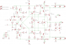
Hello Acca!Corrected:
Здравствуј Аца!!😉🙂
Acca What's this?
Did this work?🙄
Give the schemаtics if you are able?😕
cheers!
Last edited:
Hi look Post 459Hello Acca!
Здравствуј Аца!!😉🙂
Acca What's this?
Did this work?🙄
Give the schemаtics if you are able?😕
cheers!
Regards Ricky
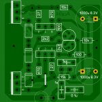
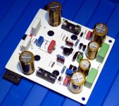
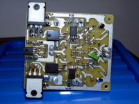
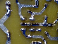
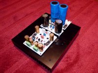
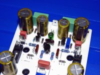
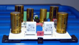
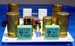
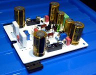
First VERSATIL 50 Board completed...some pictures for whose is interest. The last one is specially for BYRTT : the bases from BC550C/BC560C are soldered together in the same hole so the two transistors are feeded ant same time..😉😉😉
I change the input cap (4.7uf wima MKS2) for a Nichicon Muse BP 10µ/35v with a wima MKP 0.01uF.
Marc
I change the input cap (4.7uf wima MKS2) for a Nichicon Muse BP 10µ/35v with a wima MKP 0.01uF.
Marc
Attachments
Last edited:
Hi MARCFirst VERSATIL 50 Board completed...some pictures for whose is interest. The last one is specially for BYRTT : the bases from BC550C/BC560C are soldered together in the same hole so the two transistors are feeded ant same time..😉😉😉
I change the input cap (4.7uf wima MKS2) for a Nichicon Muse BP 10µ/35v with a wima MKP 0.01uF.
Marc
Great great handwork, and very nice looking, congratulations.
Cool my name gets in there, but i hope and think because you do that little layout trick, that you believe in it too.
Must say in next post 495 the last Picture gets me envious, but you deserve it by your crafts and hard Work.
When you later get to listening trials have in mind your new input capacitors, they are very audible (Maybe try same in your now running BG1-BJT so you know the color of it).
Best regards Ricky
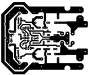
Marc those PC boards design and quality just awesome!🙂 especially known is all hand crafted😀😀
Congrat..
Today I made the layout for the LatFet version, I have some high power dual diy EXICON and Class D mosfets, I would like to test those to.
I do have a 39-0-39V 600VA transformer for that project.
If your Capmu. work with these topology well I will use that to get some voltage drop for the one pair LatFet.
To replace the BC550/560 high Hfe BJT I still need to look around on the market and also the JFet has to be replaced by BJT.
So the lay out still need some adjustment, not 100% ready.
I separated the SGR from the main GR.
I took some of your idea for the layout, it helped alot - thank you!
Soon I'll start to make the PC boards so I can test all 4 VERSION 😱
Power BJT
Toshiba
LatFet
Darlington
Greetings Gabor
Attachments
Last edited:
Thank you for your reply mr Idefixes!I think you can use them but you have to redisgn Board for TO3 output package.
Marc
Hi Acca,
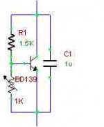
Acca provided can be replaced 3 diodes (1N4007) for bias with the transistor BD139.
What changes to the schematics following? (see schematics)
Thanks for your help!
Attachments

Last edited:
Acca, if I can use instead bdx33C/bdx34C in schematics Darlington transistors MJ11015/MJ11016?🙄
thank you!
thank you!
Acca's circuit is a class B amp. So the output stage is still in cut off mode. Adding a BD139 bias spreader will be required only if you want to run it in class AB mode. Then you will also have to deal with bias stability issues.
Acca's circuit is stripped down to a bare minimum and if that sounds good enough, then it's a great find. Has no adjustments and seems to be stable without additional components. This might be device specific I guess. So better use the circuit with parts as shown.
If you really want the bias spreader you could remove the diode string and put in the attached circuit.
Attachments
- Home
- Amplifiers
- Solid State
- FET-hex explendit amplifier