jcx, your attitude amazes me! Why so hostile to considering a measurable effect? It gets a lot harder to figure out with boutique capacitors, that stuff about capacitor squeal around 15kHz.
MIT Physics Demo - Barkhausen Effect | MIT Video
THAT is what a cored coil sounds like. I don't care whether there was hum pickup or whatever due to high impedance load.
Now take it or leave it. I certainly don't want to set up a science laboratory to investigate the effect. Though I'm not averse to simple experiments on coil interaction myself. I satisfied myself that coils (here 1mH) DO interact with each other and nearby earth planes. But I might think a couple of bucks extra spent on an aircoil worthwhile. Which is what the original poster was asking.
This makes no sense. Seriously...what are you trying to say?
Edit:
1. What is the inductance of that same inductor, not near the metal dish (which isn't a ground plane...it's floating with respect to earth potential) and again not near the metal dish and the other cored inductor attached to the tweeter.
2. The MIT demo has very little to do with cored inductors for speaker use...that's a microphone pre-amp and the pickup has several hundred turns of wire. The total gain in that high impedance system is tremendous compared to the voltage error and subsequent sound pressure from a very inefficient low impedance speakers.
Last edited:
We have had many discussions of crossover components at diyaspergers.com. 🙂
The maths seems to say that 10W wirewound/ceramic resistors are hugely lower inductance than your average tweeter, and don't get hot, so ought to work well enough.
MKP capacitors seem to be about as good as it gets even in cheapish 250V thin foil implementations at 0.1% loss. MKT polyesters are measurably worse at around 1% loss. NP electrolytics add a small sort of white noise or sibilance to female vocal that I find audible in 1:1 comparisons.
Barkhausen_effect seems like the "smoking gun" measurable problem with cored coils. FWIW, most component tolerances manifest themselves most at the -3dB or -6db point. It doubtless applies to speaker magnets too, hence perhaps the AlNiCo camp who swear those old magnets sounded better. This is in addition to non-linear hysteresis effects.
For all that, I find 1mH ferrites work well enough unless I put tank notches across them, which multiply the Q and stored energy. Then they seem to break up and sound harsh. So, overall, I think we have a case for using aircoils sometimes.
This also makes little sense...wha? How did you get to component tolerance from a molecule level phenomenon?
What was the voltage at the output of the amplifier? If you aren't dropping a significant voltage across the inductor then you won't be able to observe the effects of the inductance changing as it goes in and out of saturation, which is the mechanism that causes the distortion.
Fwiw I've tested an Erse 5mh and saturation was in the 10-20A range iirc.
The idea wasn't to test the component to the point of saturation. Instead the idea was to test the component to a point of usage that would generally be considered the limit for the rest of the system. If you test an inductor near, at or just past it's saturation limit of course the distortion will be higher. Are you really going to spend a lot of time in use there? Probably not....at 150W continuous sine wave signal level (8 Ohm) those inductors showed less distortion than almost any woofer you can think of, with that same signal level. The inductor isn't the problem...the woofer is.
I never denied the physics demos
I want to see the audio component in circuit apps measurements that show Barkhausen effect
otherwise you could be just mumbling quantum something or other and hyping Bybees or battery biased cables for all the real world applicability
the hostility is entirely directed at the hand waving
if you say "easily measured" then show the measurement in a audio component, audio context - like ferrite core inductors and loudspeaker XO
Last edited:
I never denied the physics demos
I want to see the audio component in circuit apps measurements that show Barkhausen effect
otherwise you could be just mumbling quantum something or other and hyping Bybees or battery biased cables for all the real world applicability
Like button......
https://www.klippel.de/service/search.html
so the premier site for loudspeaker modeling lists a building name on some German campus as the sole hit?
Advanced search
Search for "barkhausen"
Displaying results 1 to 1 out of 1
3_2015 BV 81%
... Measurement and Control" (by Prof. Dr. Wolfgang Klippel) Dates and Location March 23 rd to 25 th , 2015 Dresden University of Technology , Barkhausenbau, Room 205, Helmholtzstraße 18, 01069 Dresden, GERMANY The lecture will be held in English. REGISTRATION (to be submitted by March 13 th , ...
Size: 24 K, Created: 01-05-08, Modified: 10-09-10 13:36
so the premier site for loudspeaker modeling lists a building name on some German campus as the sole hit?
Standard inductor saturation test using a high current DC powersupply, mosfets and an oscilloscope, similar to this setup:how did you manage the test?
https://www.youtube.com/watch?v=Z37962AcH0k
The inductor I tested was the standard ERSE I-core 5.0mH, not the super Q. I also tested a 1.0mH and 2.5mH versions of the same ERSE series and the saturation point was exactly the same.
The 10-20A figure is where there is a serious knee in the inductance as the core saturates and the inductance drops to that of an air core. I haven't measured HD or IMD directly but you can bet that distortion will become significant above 5A at frequencies where a significant voltage is dropped across the inductor.
I have no problem using them for 6.5" and smaller drivers because distortion from the drivers themselves is already high when operating at that current.
I don't think you understood what i was trying to point out. If you operate an inductor much below the effective corner frequency you won't observe any distortion, because the inductor isn't generating any there.The idea wasn't to test the component to the point of saturation. Instead the idea was to test the component to a point of usage that would generally be considered the limit for the rest of the system. If you test an inductor near, at or just past it's saturation limit of course the distortion will be higher. Are you really going to spend a lot of time in use there? Probably not....at 150W continuous sine wave signal level (8 Ohm) those inductors showed less distortion than almost any woofer you can think of, with that same signal level. The inductor isn't the problem...the woofer is.
5.0mH+8R gives a 254Hz corner frequency and 1.5mH+4R gives 424Hz. Your test frequencies need to be significantly above 254Hz and 424Hz to get any significant non-linear distortion. If you change at least one of your test frequencies to at least double the corner frequency you'll have a better chance at observing non linear distortion as the inductor saturates.
Lets consider the case of a single 500Hz signal, 5.0mH+8R test:
-under unsaturated condition, the corner frequency is 254Hz and the inductor attenuates the signal going to the load around 6dB @ 500Hz.
-under saturated condition, lets say the effective inductance plummets to 2.0mH. Now the effective corner frequency is 637Hz and the inductor attenuates the signal going to the load around 2dB @ 500Hz.
The constant variation between -6dB and -2dB with varying current will cause non linear distortion of the 500Hz signal. In the case of a single tone, strong odd order harmonics. The same mechanism causes IMD in the presence of multiple tones. If your test frequency is too low, say 200Hz then the attenuation under both conditions is ~0dB so you don't get any significant non linear distortion produced by the inductor, even if you are saturating it.
Last edited:
BXH plane
Ok if you work with a large magnetization of the ferrite core .
But we made an audio coil with a explicit linearity on all components , for me this
means a very highest saturation of the core implied on inductor and a very small
cicle on BxH (we need a specific materials whit lo power loss on permanent magnetization tinny cycle on BxH plane )
Otherwise we made a power inductor for a general purpose .
We have had many discussions of crossover components at diyaspergers.com. 🙂
Barkhausen_effect seems like the "smoking gun" measurable problem with cored coils. FWIW, most component tolerances manifest themselves most at the -3dB or -6db point. It doubtless applies to speaker magnets too, hence perhaps the AlNiCo camp who swear those old magnets sounded better. This is in addition to non-linear hysteresis effects.
.
Ok if you work with a large magnetization of the ferrite core .
But we made an audio coil with a explicit linearity on all components , for me this
means a very highest saturation of the core implied on inductor and a very small
cicle on BxH (we need a specific materials whit lo power loss on permanent magnetization tinny cycle on BxH plane )
Otherwise we made a power inductor for a general purpose .
Last edited:
Standard inductor saturation test using a high current DC powersupply, mosfets and an oscilloscope, similar to this setup:
https://www.youtube.com/watch?v=Z37962AcH0k
The inductor I tested was the standard ERSE I-core 5.0mH, not the super Q. I also tested a 1.0mH and 2.5mH versions of the same ERSE series and the saturation point was exactly the same.
The 10-20A figure is where there is a serious knee in the inductance as the core saturates and the inductance drops to that of an air core. I haven't measured HD or IMD directly but you can bet that distortion will become significant above 5A at frequencies where a significant voltage is dropped across the inductor.
I have no problem using them for 6.5" and smaller drivers because distortion from the drivers themselves is already high when operating at that current.
I don't think you understood what i was trying to point out. If you operate an inductor much below the effective corner frequency you won't observe any distortion, because the inductor isn't generating any there.
You're right...I didn't. And you're exactly right about the test frequencies needed to see the level of distortion created by the cored inductor. I'll see if I can work up a test in the next day or two. Our former foster children are with us right now and they require a lot of attention...so I don't have the ability to just run out to my shop and do the test! (sigh)
Here's my attempt at measuring intermodulation distortion. ERSE 5.0mH I-core and 8ohm resistive load. Unfortunately the best amplifier I have available is a bit underpowered (80W@8ohm) to demonstrate this but I wanted to see if I could demonstrate saturation at all.
I didn't pay much attention to eliminating mains hum from the test setup but I chose tones at frequencies (133Hz, 1250Hz) such that the major intermodulation products (1117Hz, 1383Hz) would fall inbetween all the mains hum induced distortion/noise.
The output signal from the amplifier is around 50Vpp so a peak current of approximately 2.8-3A is achieved.
Here's the output spectrum of the amplifier under load:

And here's the spectrum across the load resistor:

So with the level of the 1250Hz tone falling 12.7dB after the inductor, we expect about the same amount of attenuation of the two intermodulation products at (1117Hz, 1383Hz) since they are suitably close, but they only fall 6.1dB and 6.2dB respectively. This means that the inductor must be introducing intermodulation products at around -106dB, possibly higher assuming they aren't in coherant phase with the intermodulation products produced by the amplifier.
I think the increase in spurious products after the inductor is probably because noise (from nearby mains cables etc) is more easily coupled into the measuring equipment when it's not connected directly to the low impedance output of the amplifier. I did note the big spur at 984Hz which seems to be intermodulation related 1250-984 = 266 which is twice 133hz.
So even at only 3A there is some saturation occuring, even if it is at an extremely low level. Of course, there is no point fussing over products at -106dB when most speakers would be introducing products at >-60dB 🙂
I didn't pay much attention to eliminating mains hum from the test setup but I chose tones at frequencies (133Hz, 1250Hz) such that the major intermodulation products (1117Hz, 1383Hz) would fall inbetween all the mains hum induced distortion/noise.
The output signal from the amplifier is around 50Vpp so a peak current of approximately 2.8-3A is achieved.
Here's the output spectrum of the amplifier under load:
And here's the spectrum across the load resistor:
So with the level of the 1250Hz tone falling 12.7dB after the inductor, we expect about the same amount of attenuation of the two intermodulation products at (1117Hz, 1383Hz) since they are suitably close, but they only fall 6.1dB and 6.2dB respectively. This means that the inductor must be introducing intermodulation products at around -106dB, possibly higher assuming they aren't in coherant phase with the intermodulation products produced by the amplifier.
I think the increase in spurious products after the inductor is probably because noise (from nearby mains cables etc) is more easily coupled into the measuring equipment when it's not connected directly to the low impedance output of the amplifier. I did note the big spur at 984Hz which seems to be intermodulation related 1250-984 = 266 which is twice 133hz.
So even at only 3A there is some saturation occuring, even if it is at an extremely low level. Of course, there is no point fussing over products at -106dB when most speakers would be introducing products at >-60dB 🙂
Last edited:
Also worth noting that there is a significant increase in the magnitude of the 3rd order harmonic of the 133Hz tone (=400Hz) after the inductor. This is not the most definitive test of that though since mains harmonics also falls at 400Hz and moving around the test cables between measurements could affect the amount of mains noise in each measurement.
There is however a few dB increase in the 2nd and 5th order harmonics of the 133Hz tone after the inductor which are reliably measurable between the mains noise.
There is however a few dB increase in the 2nd and 5th order harmonics of the 133Hz tone after the inductor which are reliably measurable between the mains noise.
Zoom around 1250Hz. The labeled frequencies are definitely inductor IMD related. I expected the 2nd order IMD products to be largest in magnitude for some reason so I was looking in the wrong places 🙂. 3rd order IMD are of course the largest - 1250+2*133 and 1250-2*133

edit: and straight out of the amp for comparison:

edit: and straight out of the amp for comparison:
Last edited:
extremely interesting 🙂
I LOVE this test.
I cant wait to get to my desktop and see on a real screen so I can compare.
Fantastic 'real world' test. The effects of mains hum being significant I guess lowers the certainty in some particular harmonics in the result, but so much can still be deduced despite that.
With reasonable if not ear splitting SPL if not with a real load, with continuous power of 60W, that particular inductors rated for 5A Isat, levels are still so low.
It certainly gives me confidence that doubling Isar in reliable manufacturers' inductor will virtually guarantee that you will never hear its THD contribution to the audio chain.
The point of current, and hence power, where any harmonic is at say -50dB or better....that would be useful information.
Taking is really simplistically, (I'm not a genius 🙂), if I assumed that 30W of continuous power would keep all distortion products under 40dB, at 30W instead of 60W...
I.could live with that performance I reckon
Last edited:
Its hard to say at what point the distortion becomes too much. A smattering of distortion products at even -60db is certainly audible as a noise floor.
It helps that the distortion is still only fairly low order, which means it will almost certainly be completely swamped by distortion at the exact same frequencies by the speaker driver(s). I should probably run a speaker under the same IMD test to put it in perspective. I'm guessing that even an exceptionally low distortion woofer like an Usher 8945 will reach the levels of IMD above at merely a few watts.
The only case I can think of where the inductors distortion might be higher than speaker driver's is if it was being used as a baffle step inductor for several large (>10") woofers, especially if they are inefficient, low impedance, or both. In that case, its probably good practice to consider using something a bit more substantial than a $13 18awg inductor for power handling reasons alone.
Last edited:
The saturation current is determined by the size and permeability of the core. Larger core will support higher current before saturation. A higher permeability core will give greater inductance for a given number of turns but will usually saturate earlier than a low permeability core. The gauge of the wiring has no effect on the saturation current but since large gauge cored inductors tend to be manufactured with larger cores the situation of unintentionally picking an inductor with a saturation current too low for the speakers being used is largely avoided based on power handling and DCR considerations alone.
I would say that the 18ga Erse inductor is adequate for almost any speakers rated at 250w or less, not because the inductor will be distortionless up to 250w but because almost every speaker rated less than 250w will have a much worse distortion profile than the inductor.
If someone goes and builds a 1000w woofer array, the distortion of the 18awg Erse inductor might present a problem, but they probably wouldn't be using it in the first place because Erse only claim it is only good for 250w, so the builder will go looking for a 1000w rated inductor which will hopefully have a suitably high saturation current and therefore have a lower distortion profile than the speakers 😉
Last edited:
TMM, interesting as your results are, I really have no idea what they mean. 😕
Did you compare these results with a reference high quality air coil?
I prefer null or bridge techniques when doing lab work. The experiment really should be designed to expose the effect we are looking for. Bridge techniques expose the DIFFERENCES!
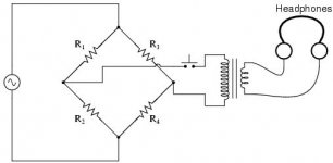
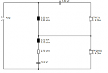
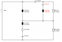
The tweeter coil in a series filter is traditionally a very critical component. I really don't know if I'll find time to do this, but the idea is that replacing the 0.3mH tweeter aircoil with a ferrite ought to produce some white noise, aka Barkhausen effect because the entire audio spectrum and power is passing through that coil, when a 1.4kHz test tone is applied to the filter. The test tone is suppressed 40db at least. Enough, I think. And doable.
You'd replace the bass with a 4 ohm resistor, and I add a notch at 1.4kHz to take out most of the test tone from the tweeter. Then you should simply hear the noise from the ferrite coming out of the tweeter. Cool eh? And it applies to a real speaker. 😎
Did you compare these results with a reference high quality air coil?
I prefer null or bridge techniques when doing lab work. The experiment really should be designed to expose the effect we are looking for. Bridge techniques expose the DIFFERENCES!
The tweeter coil in a series filter is traditionally a very critical component. I really don't know if I'll find time to do this, but the idea is that replacing the 0.3mH tweeter aircoil with a ferrite ought to produce some white noise, aka Barkhausen effect because the entire audio spectrum and power is passing through that coil, when a 1.4kHz test tone is applied to the filter. The test tone is suppressed 40db at least. Enough, I think. And doable.
You'd replace the bass with a 4 ohm resistor, and I add a notch at 1.4kHz to take out most of the test tone from the tweeter. Then you should simply hear the noise from the ferrite coming out of the tweeter. Cool eh? And it applies to a real speaker. 😎
Attachments

Last edited:
Applying some common sense (doesn't seem to be all that common)...
What would be the point in replacing 0.3mH air core with ferrite or iron cored inductor?
If lowering DCR is the aim, its not difficult to merely increase wire gauge of the air cored coil.
I know in my experience (remaining modest, in keeping with my experience), I would only consider a cored coil for inductances greater than 2 mH or so.
There seems very little point in doing otherwise.
Size and cost, copper is expensive. For DIY, your 2 mH advice is fitting. For mass produced goods, every cent counts.What would be the point in replacing 0.3mH air core with ferrite or iron cored inductor?
main problem
I think the main power is on changing of amplitude of the signal applied
Your system is LR network and on ferrite core the power lost for magnetization
change when the signal is modulate by another placed at very low frequency
Zoom around 1250Hz. The labeled frequencies are definitely inductor IMD related. I expected the 2nd order IMD products to be largest in magnitude for some reason so I was looking in the wrong places 🙂. 3rd order IMD are of course the largest - 1250+2*133 and 1250-2*133
edit: and straight out of the amp for comparison:
I think the main power is on changing of amplitude of the signal applied
Your system is LR network and on ferrite core the power lost for magnetization
change when the signal is modulate by another placed at very low frequency
- Status
- Not open for further replies.
- Home
- Loudspeakers
- Multi-Way
- Ferrite core instead of air core