removing all output tubes . check voltage on
pin 4 and 3= hi voltage to gnd if no voltage repair power supply .....after +b is ok can check pin 5 by negative voltage to gnd . ac 6.3 v between pin 7 and 2 .so if you see all voltage are same ....put 22 ohm -20watt resistor in in sires of stand by switch ....put output tube one by one and the check voltage on resistor legs . you can find defect tube by see the changing v on resistor .
pin 4 and 3= hi voltage to gnd if no voltage repair power supply .....after +b is ok can check pin 5 by negative voltage to gnd . ac 6.3 v between pin 7 and 2 .so if you see all voltage are same ....put 22 ohm -20watt resistor in in sires of stand by switch ....put output tube one by one and the check voltage on resistor legs . you can find defect tube by see the changing v on resistor .
Moved to Instruments & Amps as a more appropriate venue for tube based musical PA.
Fine - I didn't know any better

removing all output tubes . check voltage on
pin 4 and 3= hi voltage to gnd if no voltage repair power supply .....after +b is ok can check pin 5 by negative voltage to gnd . ac 6.3 v between pin 7 and 2 .so if you see all voltage are same ....put 22 ohm -20watt resistor in in sires of stand by switch ....put output tube one by one and the check voltage on resistor legs . you can find defect tube by see the changing v on resistor .
Thanks for coming in.
Sorry if this seems kind'a stupid - but is it pin 3 & 4 in the tube-sockets you mean? I'm having the meaning of 'pin' hooked up on the various pins one can find on the PCB in a receiver (up in to the 20-ies).
Br
Ole
Yes tube socket pins is what he is talking about
Good, thanks
OK, now I've had a look into it and there's a couple of obvious failures
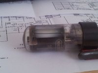
First it seems one of the 6L6'es is gone - it has melted metal on the inside of the glass (see pic).
Further visual inspection did not reveal anything, so I powered on, keeping my finger on the switch so I could switch off quickly. Which I did, because there was sparks coming from the Hum-pot, and one of the tube sockets.
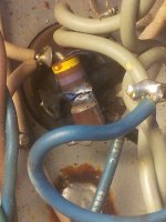
A closer look revealed a very blown resistor in the socket of the blown tube (470 ohm, pic).
So two easy targets to act on, but what would the forum do in this situation ?
I see these scenarios:
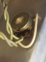
The Hum-pot - which has a little blackening by the contact surfaces (pic) - is connected by the light-green wires to the tube sockets/470 Ohms - can I expect that the sparks that came from Hum-pot will be gone after replacement of the resistor/tubes.
What would have caused the failure: first the tube went, then the resistor, or the other way around?
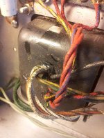
Also it needs some cleaning up - there are traces of - I don't know what - dirty (black) dust, mainly around the wiring out of the main trafo, which, by the way has a small crack at wire-entry point (pic) - should I care about that?
Should I give it a shot from the glue-gun to seal it, or just leave it be?
Lots of questions, I know.
/Ole
First it seems one of the 6L6'es is gone - it has melted metal on the inside of the glass (see pic).
Further visual inspection did not reveal anything, so I powered on, keeping my finger on the switch so I could switch off quickly. Which I did, because there was sparks coming from the Hum-pot, and one of the tube sockets.
A closer look revealed a very blown resistor in the socket of the blown tube (470 ohm, pic).
So two easy targets to act on, but what would the forum do in this situation ?
I see these scenarios:
- replace only the failed parts
- replace all 4 tubes and corresponding 470 ohm res?
- replace all 4 tubes and the 4 470 Ohms stepping up the Wattage to 3 or 5 watts?
- take it further and replace all caps too?
- other?
The Hum-pot - which has a little blackening by the contact surfaces (pic) - is connected by the light-green wires to the tube sockets/470 Ohms - can I expect that the sparks that came from Hum-pot will be gone after replacement of the resistor/tubes.
What would have caused the failure: first the tube went, then the resistor, or the other way around?
Also it needs some cleaning up - there are traces of - I don't know what - dirty (black) dust, mainly around the wiring out of the main trafo, which, by the way has a small crack at wire-entry point (pic) - should I care about that?
Should I give it a shot from the glue-gun to seal it, or just leave it be?
Lots of questions, I know.
/Ole
Attachments
The tube most likely failed and took the screen resistor (470R resistor between pins 6 & 4) with it. I would replace all four 470R resistors with 2 watt metal oxide flameproof resistors. And replace all power tubes with a matched quad of 6L6GC's.
What I would do first is remove the damaged 470R screen resistor because it looks like it could be arcing over to one of the other tube pins. Then remove all tubes from the amp, with the dim bulb tester turn the amp on and see if the hum pot is still sparking. If there are no sparks or smoke measure heater voltages between pins 2 and 7 of power tubes and between pins 3&4 (3&4 are connected together) and 9 of the preamp tubes, should be a tad higher than 6.3 because it is unloaded. Next check negative bias voltage at pin 5 of all power tubes, should be around -45v.
That should be a good place to start, if everything is ok you can then order some tubes and screen resistors and maybe some caps.
all 4 power tubes, only - correct? - not every and each tube?The tube most likely failed and took the screen resistor (470R resistor between pins 6 & 4) with it. I would replace all four 470R resistors with 2 watt metal oxide flameproof resistors. And replace all power tubes with a matched
What I would do first is remove the damaged 470R screen resistor because it looks like it could be arcing over to one of the other tube pins. Then remove all tubes from the amp
Sorry I have to ask a question like this, but I'd rather be certain, since this type of equipment is new to me.
, with the dim bulb tester turn the amp on and see if the hum pot is still sparking. If there are no sparks or smoke measure heater voltages between pins 2 and 7 of power tubes and between pins 3&4 (3&4 are connected together) and 9 of the preamp tubes, should be a tad higher than 6.3 because it is unloaded. Next check negative bias voltage at pin 5 of all power tubes, should be around -45v.
Thanks, 'bird, I think your approach is very good advise and I will follow it to the letter
, except when the DBT is in the circuit, it sucks up too much power to activate the error - it didn't occur until I removed it, and the amp received the full voltage - before that there was no indications of electric activity. My DBT is with the option of 1 or 2 bulbs (I only have 70 W and a 13 W low energi bulb). With the 2 bulb version the 13W bulb lights up and the 70W stays un-lit, and I measure about 60V at the red (340V) wire off the main trafo, and in the 1 bulb (70W) version i get 195V(semi light in bulb), and only when DBT isn't used I get 335V, but that was when I saw sparks and I powered off instantly. However I will do the test with the DBT in circuit again, both before and after I have replaced the 470 Ohms, and with the fried screen resistor pulled.
Regarding 3&4 being inter-connected: Am I misreading the schematic - I don't see where 3&4 connects? If it matters?
I do see the -45V on the number 5 pins, and will check on them.
One more thing: Would you replace the hum-pot just because of the sparks it has seen, or not?
I have found this: Potmeter - 100 ohm lin. (Ø6mm) (danish webshop but description in english.)
It seems a usable replacement, even with the shaft, which can be shortened as/if need be.
That should be a good place to start, if everything is ok you can then order some tubes and screen resistors and maybe some caps.
Since there is one verified failed tube, and the rest are of same age, wouldn't you think it makes sense to order a full quad of 6L6GC's. ? I suppose tubes have a limited lifespan and there are near their end?
Attachments
Last edited:
all 4 power tubes, only - correct? - not every and each tube?
I would remove all the tubes because the hum pot that is sparking is for the heater circuit, and you don't want to damage the preamp tubes.
except when the DBT is in the circuit, it sucks up too much power to activate the error - it didn't occur until I removed it, and the amp received the full voltage - before that there was no indications of electric activity.
Yes the voltage isn't enough to cause a spark with the bulb tester in circuit, but you can probe the hum pot to check for any voltages that shouldn't be there. You should only have low voltage AC and no high voltage DC. I would just use the single bulb 70w tester for this.
My DBT is with the option of 1 or 2 bulbs (I only have 70 W and a 13 W low energi bulb). With the 2 bulb version the 13W bulb lights up and the 70W stays un-lit, and I measure about 60V at the red (340V) wire off the main trafo, and in the 1 bulb (70W) version i get 195V(semi light in bulb), and only when DBT isn't used I get 335V, but that was when I saw sparks and I powered off instantly.
You will not have full power when using the DBT but you will get enough to do some voltage testing. For an amp this size I would use a 100watt bulb but the 70watt will work fine......the 13w bulb has too much series resistance to be useful.
Regarding 3&4 being inter-connected: Am I misreading the schematic - I don't see where 3&4 connects?
I am sorry for the confusion (I was in the hospital with a collapsed lung and on lots of morphine when posting) but the preamp tubes heaters have pins 4&5 connected. So again for the power tubes heater filaments measure AC voltage between pins 2 and 7. And for the preamp tubes measure between 4&5 and 9. Make sure there is no DC here.
I do see the -45V on the number 5 pins
This is good and indicates that the amps bias is fine and the tube was probably just old and failed.
One more thing: Would you replace the hum-pot just because of the sparks it has seen, or not?
With no power check resistance while sweeping the wiper, if it works correctly no need to replace.
OK, all tubesI would remove all the tubes because the hum pot that is sparking is for the heater circuit, and you don't want to damage the preamp tubes.
OK, will do.Yes the voltage isn't enough to cause a spark with the bulb tester in circuit, but you can probe the hum pot to check for any voltages that shouldn't be there. You should only have low voltage AC and no high voltage DC. I would just use the single bulb 70w tester for this.
You will not have full power when using the DBT but you will get enough to do some voltage testing. For an amp this size I would use a 100watt bulb but the 70watt will work fine......the 13w bulb has too much series resistance to be useful.
Ohh, I'm really sorry to hear your not well.I am sorry for the confusion (I was in the hospital with a collapsed lung and on lots of morphine when posting) but the preamp tubes heaters have pins 4&5 connected. So again for the power tubes heater filaments measure AC voltage between pins 2 and 7. And for the preamp tubes measure between 4&5 and 9. Make sure there is no DC here.
That said I think you did a pretty good job answering when you're in pain and under the influence of strong medicine.
I'll have to take a closer look at the diagram, and learn to this type - it's a little different from the schematics I just learned reading, doing my receiver, which didn't have any tubes.
I'll try and find the readings you suggest.
I was unclear at this item - I didn't take any measurement, I only found the -45V on the diagram 😀This is good and indicates that the amps bias is fine and the tube was probably just old and failed.
Good, I will check this.With no power check resistance while sweeping the wiper, if it works correctly no need to replace.
Now, get some rest and get well soon!
Thanks
ALL tubes pulled out.
The 1500R at pin 5, that is below the fried 470R, reads 1650 Ohm - within 10%.
Checking for -45V at the 80uf/75V cap, 3.3K resistor:
Using DBT, on standby, no sparks, bulb is dim: -55V
Using DBT, standby off, no sparks, bulb is dim: -56V
This is in my opinoin a too large deviation from specs, perhaps a resistor has gone ? One of the 68Ks or the 3.3K ?
I'm not sure how to test the hum-pot, but I think it must be damaged. With one test lead of the DMM (multimeter) on the center lug, and the other on either of the two other, there is only readings of approx. 5 Ohms in both the extreme positions (Max or Min), as well as there only the beep when DMM is set to sound the tone for connectivity, here. In between Ohm meter reads 'OL', or no tone, when DMM is set to that.
I would say this pot must be fried?
Regarding the various tubes I need a little education.
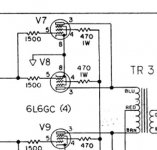
I have pulled the 4 6L6GC (Power tubes ?), which I see as designated as V7, V8, V9 and V10 - correct?
Physically I believe that V10 is the one placed at end, where the power wire enters the metal housing - correct?
I believe I've decoded the way tubes V1 - V6 are depicted on the diagram - they are split up in a V#A-1,2,3, and a V#B-6,7,8 for better readability - correct?
Regarding preamp tubes - are they all of the 6 V1-V6, or only some of them? If only some, what type would the remaining be called?
Also I am unable to determine the numbering of the pins on the smaller (preamp, 12AX7A, 12AT7, 7025) tubes. If it is the as the power tubes I would guess that:
when looking at the bottom of the tube, place the empty spot in 12-oclock position, pin #1 will be in one-oclock posistion, and then increasing pin number going round clockwise?
It's getting late and I loose focus, will continue with reading voltages on the power tubes heater filaments between pins 2 and 7. And for the preamp tubes measure between 4&5 and 9.
The 1500R at pin 5, that is below the fried 470R, reads 1650 Ohm - within 10%.
Checking for -45V at the 80uf/75V cap, 3.3K resistor:
Using DBT, on standby, no sparks, bulb is dim: -55V
Using DBT, standby off, no sparks, bulb is dim: -56V
This is in my opinoin a too large deviation from specs, perhaps a resistor has gone ? One of the 68Ks or the 3.3K ?
I'm not sure how to test the hum-pot, but I think it must be damaged. With one test lead of the DMM (multimeter) on the center lug, and the other on either of the two other, there is only readings of approx. 5 Ohms in both the extreme positions (Max or Min), as well as there only the beep when DMM is set to sound the tone for connectivity, here. In between Ohm meter reads 'OL', or no tone, when DMM is set to that.
I would say this pot must be fried?
Regarding the various tubes I need a little education.
I have pulled the 4 6L6GC (Power tubes ?), which I see as designated as V7, V8, V9 and V10 - correct?
Physically I believe that V10 is the one placed at end, where the power wire enters the metal housing - correct?
I believe I've decoded the way tubes V1 - V6 are depicted on the diagram - they are split up in a V#A-1,2,3, and a V#B-6,7,8 for better readability - correct?
Regarding preamp tubes - are they all of the 6 V1-V6, or only some of them? If only some, what type would the remaining be called?
Also I am unable to determine the numbering of the pins on the smaller (preamp, 12AX7A, 12AT7, 7025) tubes. If it is the as the power tubes I would guess that:
when looking at the bottom of the tube, place the empty spot in 12-oclock position, pin #1 will be in one-oclock posistion, and then increasing pin number going round clockwise?
It's getting late and I loose focus, will continue with reading voltages on the power tubes heater filaments between pins 2 and 7. And for the preamp tubes measure between 4&5 and 9.
ALL tubes pulled out.
The 1500R at pin 5, that is below the fried 470R, reads 1650 Ohm - within 10%.
Checking for -45V at the 80uf/75V cap, 3.3K resistor:
Using DBT, on standby, no sparks, bulb is dim: -55V
Using DBT, standby off, no sparks, bulb is dim: -56V
This is in my opinoin a too large deviation from specs, perhaps a resistor has gone ? One of the 68Ks or the 3.3K ?
You will have -55 volts on one side of the 3.3k resistor and -45 on the other, double check. Or better check for -45 directly at pin 5 for each power tube because you want to make sure the negative bias is getting to the tubes.
I'm not sure how to test the hum-pot, but I think it must be damaged. With one test lead of the DMM (multimeter) on the center lug, and the other on either of the two other, there is only readings of approx. 5 Ohms in both the extreme positions (Max or Min), as well as there only the beep when DMM is set to sound the tone for connectivity, here. In between Ohm meter reads 'OL', or no tone, when DMM is set to that.
I would say this pot must be fried?
Are you sure you are not reading 50? You will have to remove the wiring to the pot to test it because you will be reading both halves of the pot in parallel through the transformer which would be 50. Or if the pot is 10ohms than 5 would be right on the money. The pot is probably fine but to be sure remove the wiring and check it.
Regarding the various tubes I need a little education.
I have pulled the 4 6L6GC (Power tubes ?), which I see as designated as V7, V8, V9 and V10 - correct?
Yes
Physically I believe that V10 is the one placed at end, where the power wire enters the metal housing - correct?
Yes
I believe I've decoded the way tubes V1 - V6 are depicted on the diagram - they are split up in a V#A-1,2,3, and a V#B-6,7,8 for better readability - correct?
Yes
Regarding preamp tubes - are they all of the 6 V1-V6?
Yes
Also I am unable to determine the numbering of the pins on the smaller (preamp, 12AX7A, 12AT7, 7025) tubes. If it is the same as the power tubes I would guess that:
when looking at the bottom of the tube, place the empty spot in 12-oclock position, pin #1 will be in one-oclock posistion, and then increasing pin number going round clockwise?
That is correct.
It's getting late and I loose focus, will continue with reading voltages on the power tubes heater filaments between pins 2 and 7. And for the preamp tubes measure between 4&5 and 9.
Cool keep up the good work and I will try and help you as much as I can 🙂
Last edited:
OK, ready for some voltages - I would say they all look good:
Pin 5, checking for -45V:
V7 -45.5V
V8 -45.5V
V9 -45.8V
V10 -45.6V
You were right about the -55V - I was misreading the schematic
Hum-pot:
De-soldered, but even so readings are all over the place, from 0 over OL to Mega, and below 10, when turning from minimum to max.
Also there is no beep when connection-test is selected on DMM - Fried? Might as well replace with the one I referred to previously?
Potmeter - 100 ohm lin. (Ø6mm)
Following readings are with hum-pot removed, but pot-wires connected as they are soldered on the lugs, to keep curcuit closed.
Between 2 and 7:
V7 6.0 VAC, 0 VDC
V8 6.0 VAC, 0 VDC
V9 6.0 VAC, 0 VDC
V10 6.0 VAC, 0 VDC
Between 4&5 and 9
V1 6.0 VAC, 0 VDC
V2 6.0 VAC, 0 VDC
V3 6.0 VAC, 0 VDC
V4 6.0 VAC, 0 VDC
V5 6.0 VAC, 0 VDC
V6 6.0 VAC, 0 VDC
I believe I've completed the tests you suggested by now, so I guess it's time to decide on replace the 4 470R, the 4 6L6GCs and the hum-pot?
PS: I will be away on a little trip till tuesday, so there won't be any activity between tormorrow and tuesday.
Hope your'e getting better
Great!
Was the 6VAC reading taken while using the DBT? If yes then take another reading without using the DBT. The reason for this is because without any load you should have closer to 7VAC on that winding without the DBT, but if you were using the DBT than the voltages will be a little lower and the 6VAC would be normal.
I am better and thanks for your kind regards
It was with the DBT in use.Great!
Was the 6VAC reading taken while using the DBT? If yes then take another reading without using the DBT. The reason for this is because without any load you should have closer to 7VAC on that winding without the DBT, but if you were using the DBT than the voltages will be a little lower and the 6VAC would be normal.
So if the readings without DBT is closer to 7 VAC, would you say go ahead and order the components I mentioned, including the hum-pot?
Good to hearI am better and thanks for your kind regards
It was with the DBT in use.
So if the readings without DBT is closer to 7 VAC, would you say go ahead and order the components I mentioned, including the hum-pot?
Yes.
What I would do is install two of the 6L6GC power tubes (not the broken one of course) in the amp along with all the preamp tubes and turn her on. You would install one 6L6GC in V7 and the other 6L6GC in V10 unless V7 or V10 was the socket with the bad 470R then you would put them in V8 and V9. It won't do any harm you will just be getting about 3db less volume out of the amp. People do this with 100 watt amps like Marshalls and Fender Twin Reverbs all the time to get less headroom.
To be clear I was recommending you do this before you order parts to be sure nothing expensive like the output transformer isn't broken.
To be clear I was recommending you do this before you order parts to be sure nothing expensive like the output transformer isn't broken.
Right, makes good sense
And in extension of your previous post (#38), the broken 470R and the tube that look different from the other three, is V8 (nr. 3 from the edge). I assume that the tube blew the resistor, so no need to put that in and blow another resistor?
But... It just ocurred to me, that what I measured in #35 was all the same voltage source, since all the pins 4&5/9 and 2/7 is on the light green wire set all the way from the pilot light on the front, through to V1 - there must be something I am missing here?
Anyway, my friend will drop by the electronics shop tomorrow and pick up a handful 470's and the pot for the hum.
Then some time next week I will mount a new 470R in V8, and then do the two-step test, first with (good) tubes in V7,V10, then move them to V8,V9.
Then what would I be looking for? Only the amp is with me - do we need the speakers and a string instrument
 to test it?
- Status
- Not open for further replies.
- Home
- Live Sound
- Instruments and Amps
- Fender PA100 - smoke -> no sound