Yes that tube is toasted. Could have been defective to begin with or it was a bad connection with the tube socket, the amp seems fine now, no red plates anymore?
Yes you could continue testing with an old tube just keep a close watch making sure if the plates starts glowing red to shut her down. And yes recheck bias.
Yes you could continue testing with an old tube just keep a close watch making sure if the plates starts glowing red to shut her down. And yes recheck bias.
Testing w. old tubes
OK, now I tested with new tubes in V7,8 and old tubes in V9,10.
Resistance reading, red probe on pin 3, black on standby:
V7: 38.9 Ohm
V8: 38.6 Ohm
V9: 36.3 Ohm
V10: 36.5 Ohm
Voltage reading, pin 3 <> GND
V7: 455 V
V8: 456 V
V9: 456 V
V10: 456 V
Preparing for bias:
2/3 of 30 watts= 20w.
20W(VA)/456V = 0.0439 Amp
times 2 = 0.0878 A
U=R*I:
Voltage= 38.7 ohm * 0.088 A = 3.33 V for V7,V8
Voltage= 36.4 ohm * 0.088 A = 3.20 V for V9,V10
Red probe on pin 3, black on standby, turning bias pot in the full range:
V7: -0.83 - -2.34 volts
V8: -0.83 - -2.34 volts
V9: +- 0.0003 volts ?
V10: +- 0.0003 volts ?
Should have reversed the probes to get positive readings, but doesn't matter, values would be the same.
But these reading seems far from useful, particularly the practically zero readings for V9,10 is confusing 😕
While testing all tubes are looking fine, with a delicate orange glow in the small center threads. They are hot ranging from "can touch briefly" on V9, V10, to "almost getting burnt, with even a very brief touch" at V7.
Kind'a lost here.
Can you take a nice clear picture of the power tube sockets (6L6)? Maybe even one picture of V7 V8 and one of V9 V10. The side with the wires attached of course.
If there is no voltage drop from the standby switch to Pin 3 it means there is no current flowing. Something is not attached somewhere on that side. Me thinks.
If there is no voltage drop from the standby switch to Pin 3 it means there is no current flowing. Something is not attached somewhere on that side. Me thinks.
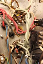
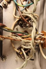
Thanks. Those sockets all look to be wired properly. The cathodes are certainly grounded! The Bias voltage is correct!
Do the tube sockets look nice and shiny clean where the tube pins go in?
Do the tube sockets look nice and shiny clean where the tube pins go in?
Yes, I believe the wiring is good.Thanks. Those sockets all look to be wired properly. The cathodes are certainly grounded!
😕 Are you readning my post correctlyThe Bias voltage is correct!
This is what I was looking for according to famousmockingbird,
Voltage= 38.7 ohm * 0.088 A = 3.33 V for V7,V8
Voltage= 36.4 ohm * 0.088 A = 3.20 V for V9,V10
but this was what I read:Voltage= 36.4 ohm * 0.088 A = 3.20 V for V9,V10
V7: -0.83 - -2.34 volts
V8: -0.83 - -2.34 volts
V9: +- 0.0003 volts ?
V10: +- 0.0003 volts ?
V8: -0.83 - -2.34 volts
V9: +- 0.0003 volts ?
V10: +- 0.0003 volts ?
I would say tubes 9, 10 has a problem with readings stuck below a few millivolts...
Do the tube sockets look nice and shiny clean where the tube pins go in?
shiny and shiny, well, when I did the retension, what I could see was just the round opening, not down and inside, where the pin fits in. It may be that they aren't clean, considering the amp about 40 years old, but the pins seems to have a snug fit in the sockets now, so I suppose a little dirt (if any present) won't prevent good contact - but I would have find a way to clean them to be sure...
Hi:
"Are you readning my post correctly" Yes
In post # 35 (a while back) you did measure the bias voltage on pin #5 of each tube and it looked to be exactly correct. To me the only other way V9 and V10 would not be drawing current would be if the cathodes were not connected to ground. The pictures verify that the cathodes are indeed connected to ground.
Here is what I would do. You have become more comfortable with measuring high voltages. So have the negative probe of your voltmeter connected to ground with a clip then with one hand behind your back turn on the amp with the tubes in and go around each socket pin on all four tubes and record the voltage...the problem should be quite apparent if one side is drawing current and not the other side. (let it warm up for a minute and have the standby switch on)
Well, pulling all tubes and do some voltage readings.
Looking for -45/-56 V around the 3.3 KOhm
reading: -50/-61 V (adjustable between -54/-63 w bias pot)
reading pins #5:
V7: -49.9 V
V8: -49.9 V
V9: -49.4 V
V10: -49.4 V
Same pattern as first reading in post #35, but 5 volts higher - an indication of a damaged resistor, perhaps?
Voltages, all pins:
An observation:
The 1.8 KOhm at TR1-red-blue wire is a 1 KOhm (brown,black,red,gold, and tests to this value; yes lifted a leg) - factory mod, user mod or sloppy repair? It has a newer look to it - smaller, rounded ends and shiny surface as opposed to the originals (larger, square end, matt surface).
The resistor must have been here for all years the amp has been in Twans possesion, so my guess is it isn't a significant change, but more knowledgeable may correct me here?
Testet the 80 µF cap while I was at it; reads 83.5 µF (good).
Not sure if this brings any leads 😕
Looking for -45/-56 V around the 3.3 KOhm
reading: -50/-61 V (adjustable between -54/-63 w bias pot)
reading pins #5:
V7: -49.9 V
V8: -49.9 V
V9: -49.4 V
V10: -49.4 V
Same pattern as first reading in post #35, but 5 volts higher - an indication of a damaged resistor, perhaps?
Voltages, all pins:
HTML:
Pin#:	  1	  2	  3	  4	  5	  6	  7
V7:	-49.7	0.0	+454	+453	-49.7	+454	0.0
V8:	-49.7	0.0	+455	+455	-49.9	+456	0.0
V9:	-49.5	0.0	+458	+456	-49.6	+456	0.0
V10: -49.3 0.0 +455 +454 -49.3 +455 0.0The 1.8 KOhm at TR1-red-blue wire is a 1 KOhm (brown,black,red,gold, and tests to this value; yes lifted a leg) - factory mod, user mod or sloppy repair? It has a newer look to it - smaller, rounded ends and shiny surface as opposed to the originals (larger, square end, matt surface).
The resistor must have been here for all years the amp has been in Twans possesion, so my guess is it isn't a significant change, but more knowledgeable may correct me here?
Testet the 80 µF cap while I was at it; reads 83.5 µF (good).
Not sure if this brings any leads 😕
Double check continuity between pin 8 and ground for V9 and V10, or even resolder the connections. Other than that the voltages there seem fine. Also check the sockets again.
The 1K is fine, only way you would have to change it higher is if you can't bias the tubes warm enough to get rid of crossover distortion.
The 1K is fine, only way you would have to change it higher is if you can't bias the tubes warm enough to get rid of crossover distortion.
Can you do those measurements again with the tubes in? Have your speaker plugged in. How many ohms do you measure across the speaker (output)? Maybe measure that first before you turn on the amp.
Mockingbird:
I did a beep-test with the DMM, with one probe on the chassis, and the other traveling all 8 pins on all 4 sockets, and I get a good beep on all 4 pin #8 (only).
================================
All tubes in,
Looking for -45/-56 V around the 3.3 KOhm
reading: -49.9/-61.3 V
reading pin 5:
V7: -49.4 V
V8: -49.2 V
V9: -48.8 V
V10: -49.0 V
Voltages, all pins:
----------------------------------
"Can you do those measurements again with the tubes in? Have your speaker plugged in. How many ohms do you measure across the speaker (output)? Maybe measure that first before you turn on the amp."
----------------------------------
Resistance at speaker-output:
Power on, tubes in, speakers in: No reading (0.00 Ohm)
Power off, tubes in, speakers in: Sp1: 0.8 Ohm , Sp2: 0.3 Ohm
Testing speaker resistance at the (disconnected) plugs reads 8,3 Ohm on both speakers.
Question:
Can the it be that the off-the-scale bias reading is related to the fact, that there is two different tube pairs in the amp? (New in V7,8, old in V9,10)
I did a beep-test with the DMM, with one probe on the chassis, and the other traveling all 8 pins on all 4 sockets, and I get a good beep on all 4 pin #8 (only).
================================
All tubes in,
Looking for -45/-56 V around the 3.3 KOhm
reading: -49.9/-61.3 V
reading pin 5:
V7: -49.4 V
V8: -49.2 V
V9: -48.8 V
V10: -49.0 V
Voltages, all pins:
HTML:
no speakers
Pin#:	  1	  2	  3	  4	  5	  6	  7
V7:	-49.3	0.0	+445	+445	-49.1	+445	0.0
V8:	-49.5	0.0	+449	+450	-49.4	+447	0.0
V9:	-48.8	0.0	+449	+449	-48.8	+449	0.0
V10:	-48.7	0.0	+445	+445	-49.0	+445	0.0

speakers in
V7:	-49.5	0.0	+448	+445	-49.0	+446	0.0
V8:	-49.4	0.0	+449	+449	-49.4	+450	0.0
V9:	-49.0	0.0	+451	+451	-49.3	+451	0.0
V10:	-49.1	0.0	+449	+448	-49.2	+452	0.0
----------------------------------
"Can you do those measurements again with the tubes in? Have your speaker plugged in. How many ohms do you measure across the speaker (output)? Maybe measure that first before you turn on the amp."
----------------------------------
Resistance at speaker-output:
Power on, tubes in, speakers in: No reading (0.00 Ohm)
Power off, tubes in, speakers in: Sp1: 0.8 Ohm , Sp2: 0.3 Ohm
Testing speaker resistance at the (disconnected) plugs reads 8,3 Ohm on both speakers.
Question:
Can the it be that the off-the-scale bias reading is related to the fact, that there is two different tube pairs in the amp? (New in V7,8, old in V9,10)
Question:
Can the it be that the off-the-scale bias reading is related to the fact, that there is two different tube pairs in the amp? (New in V7,8, old in V9,10)
Yes they could be at two different ends of the current/bias spectrum and possibly causing one pair to be biased so cold they are not conducting. Try and use the bias balance pot to make the voltage at pin #5 for V9/V10 more positive than V7/V8 and see if that helps.
Since you have the same bias voltage at pin#5 for both sides at the moment you could just swap them, meaning put the old tubes in V7/V8 and the new in V9/V10 and see if the problem follows the tubes.
if the problem doesn't follow the tubes i'd start looking at the phase inverter in particular the .022 caps that couple the signal to the output.
Thanks for contributing, Turk 
Yes, I've been thinking a swap of position should be tried, but I never got to it - till now 😉
here - old tubes in V7,8 and new tubes in V9,10.
Looking at bias, red probe on std.by, black on pins #3:
V7: fluctuates <= a few millivolts
V8: fluctuates <= a few millivolts
V9: 0.83 - 2.34 volts (min - max)
V10: 0.83 - 2.34 volts (min - max)
So bias voltages follows the tubes - maybe this isn't a valid tube combination?
could you explain why your measuring the bias with respect to the plate?
Ahh, no - am I doing this the wrong way?
I can not rule out that I may have misunderstood/forgot how to do the reading correctly (noob)

in post #59 i believe famousmockingbird was pretty clear that the measurements should be with respect to chassis ground.
if you don't follow directions or understand them things can go south fast!
if you don't follow directions or understand them things can go south fast!
in post #59 i believe famousmockingbird was pretty clear that the measurements should be with respect to chassis ground.
Well, I'm leaning on post #49:
You measure across the same place you took the DC resistance measurements. This would be the standby switch and pin 3 of power tubes, again you will have same reading for pin 3 on V7/V8 as well as V9/V10.
if you don't follow directions or understand them things can go south fast!
Agree to that
A bit confused here 😕
- Status
- Not open for further replies.
- Home
- Live Sound
- Instruments and Amps
- Fender PA100 - smoke -> no sound