And in extension of your previous post (#38), the broken 470R and the tube that look different from the other three, is V8 (nr. 3 from the edge). I assume that the tube blew the resistor, so no need to put that in and blow another resistor?
No throw that tube in the trash.
But... It just ocurred to me, that what I measured in #35 was all the same voltage source, since all the pins 4&5/9 and 2/7 is on the light green wire set all the way from the pilot light on the front, through to V1 - there must be something I am missing here?
You have the right of things they are from the same source, testing at the sockets is just making sure the wiring to the tubes is ok.
Anyway, my friend will drop by the electronics shop tomorrow and pick up a handful 470's and the pot for the hum.
Then some time next week I will mount a new 470R in V8, and then do the two-step test, first with (good) tubes in V7,V10, then move them to V8,V9.
Before you buy anything from the electronic shop take any two of the remaining three 6L6GC's and install them in V7 and V10. They are not broken just old and tired, this is ok for testing because you won't be pushing them hard. Read my last note in this post before doing this.
Then what would I be looking for? Only the amp is with me - do we need the speakers and a string instrumentto test it?
You will need a speaker or an 8R dummy load to test the amp when you install the power tubes. You don't need an instrument but some kind of source like music or whatever will work. DO NOT run a signal through the amp when you install the 6L6GC's without a speaker or a dummy load hooked up.
Resistor replaced
Ok, back from the trip I have replaced the resistor, as well as the hum-pot.
I re-installed the 6 preamp tubes and a pair of good 6L6 in V7 and in V10, powered on with DBT, and all looked well (if some light in the DBT bulb is acceptable) - no smoke, no sparks 🙂
Then repeat with tubes in V8,V9, and then same without DBT - all peaceful, and fine - no unwanted fumes or noises. The 6L6s had a low glow in the center - a little dimmed with the DBT in use.
Before powering on this time I changed the power switch from 220V to 230V, which is the actual voltage (I checked) coming out of the wall outlets.
For further test with an input source, I should have either 8 ohm speakers or a dummy 8 ohm load in place - I get that.
If I do the dummy 8 ohm load, do i take an 8 ohm resistor and connect the leads to the two contact surfaces inside the amp?
Or the neat way to do it would be if I had (I don't) a 6 mm mono jack, where I could connect the 8 ohm res to its contact-lugs, and plug it into the output socket?
There are 2 outputs - do they both need to be loaded, or will loading just one, ensure no harm is done?
My friend suggests that in stead of replacing with 4 identical tubes, why not replace with two different pairs, to have a sort of two-tone amp. Is this a possibility?
If yes, what would be a suitable alternative to one pair of the 6L6GCs?
Anybody, feel free to chip in with your preference, if this makes sense at all.
If I do the dummy 8 ohm load, do i take an 8 ohm resistor and connect the leads to the two contact surfaces inside the amp?
Not sure what you mean by the two surfaces inside the amp but the speaker jack is a shorting type so you would have to open the contact first before placing the load across the secondary. Make sure you use an adequately sized resistor if you plan on testing the amp with an input signal and a dummy load. If you just want to check voltages with no input signal you can get away with a much smaller resistor for the dummy load. BUT if you do plan on testing for full output power against a resistive load make sure you use a 100 watt rated dummy load.
Or the neat way to do it would be if I had (I don't) a 6 mm mono jack, where I could connect the 8 ohm res to its contact-lugs, and plug it into the output socket?
This is how I do it.
There are 2 outputs - do they both need to be loaded, or will loading just one, ensure no harm is done?
Just the one closest to the switches will do.
My friend suggests that in stead of replacing with 4 identical tubes, why not replace with two different pairs, to have a sort of two-tone amp. Is this a possibility?
If yes, what would be a suitable alternative to one pair of the 6L6GCs?
Are you talking about a totally different type of tube like an EL34 or a different brand of 6L6GC's? If you are talking about a different type of tube then yes you can do that as long as they are biased properly. This leads me into my next topic, if you are putting new tubes in this thing make sure you check the bias of the new valves so they don't prematurely fail if biased too hot, or be biased too cold and sound bad. BTW you do not have a bias pot in that amp, only a balance pot. If the valves are not happy in this amp at the current bias setting you will have to change a resistor😱
Hi there ..
here's the amplifier friend speaking 🙂 You did a great job so far .. i'm impressed ..
i was looking at 6L6 rør - Thomann Danmark where there's several 6L6 tubes ; it would be great if there could be 2 pairs of different tubes of the 6L6 type.
here's the amplifier friend speaking 🙂 You did a great job so far .. i'm impressed ..
i was looking at 6L6 rør - Thomann Danmark where there's several 6L6 tubes ; it would be great if there could be 2 pairs of different tubes of the 6L6 type.
Not sure what you mean by the two surfaces inside the amp but the speaker jack is a shorting type so you would have to open the contact first before placing the load across the secondary. Make sure you use an adequately sized resistor if you plan on testing the amp with an input signal and a dummy load. If you just want to check voltages with no input signal you can get away with a much smaller resistor for the dummy load. BUT if you do plan on testing for full output power against a resistive load make sure you use a 100 watt rated dummy load.
If I do the dummy 8 ohm load, do i take an 8 ohm resistor and connect the leads to the two contact surfaces inside the amp?
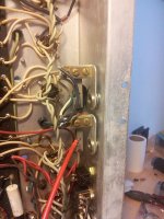
I mean connect the 8 ohm to where the red gripper is hooked, and to the other contact surface in the plug-socket (ground?) (Pic-1)
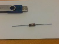
I found a couple of 8.2 ohm (gray,red,gold,silver - pic-2 USB-stick for comparison of size) - I guess it will suffice?
This is how I do it.
Just the one closest to the switches will do.
Are you talking about a totally different type of tube like an EL34 or a different brand of 6L6GC's? If you are talking about a different type of tube then yes you can do that as long as they are biased properly. This leads me into my next topic, if you are putting new tubes in this thing make sure you check the bias of the new valves so they don't prematurely fail if biased too hot, or be biased too cold and sound bad. BTW you do not have a bias pot in that amp, only a balance pot. If the valves are not happy in this amp at the current bias setting you will have to change a resistor😱
Regading different tube pairs:
Good point about bias. There is a (1) pot - the "OUTPUT BALANCE" just left of "TR2" on the schematic. Is that the bias adjustment pot?
Looks like it balances V7,V8 against V9,V10?
But for the test I had V7-V10 and V8-V9 as pairs - a little confused (by myself 😛 ) here.
But I think I need some guidance when it comes to adjusting output/bias.
At this point we (Twan and I) need to determine if Twan's idea of mixing two types af tubes is a valid option.
And if so, which tubes can be used and still have the amp working in good order, ie. can different tubes be bias-adjusted without problems.
Hey guys,
I bet you two can't wait to get this amp rockin! It's gonna be loud🙂
Anyway I don't see any pictures 😕
Yes you can use different 6L6's, even if they all don't match exactly for current draw you can adjust with the bias balance pot. When you order get at least two matched pairs, it will make things easier if they all match for current draw, but the minimum you would want is two matched pairs.
And about the bias pot, you are correct in that it balances V7 and V8 with V9 and V10. V7 and V8 are in parallel and conduct one waveform while V9 and V10 are in parallel and conduct a waveform 180 degrees apart from what V7 and V8 see, this is the whole push pull topology.
To check the bias you are going to want to measure the DC resistance from the output transformers center tap to pin 3 of V7-V10, V7 and V8 should have the same reading as well as V9 and V10 should also be the same. What you are going to do is measure the voltage drop across these test points and then divide by the measurement you get in the resistance test.
For example you measure from the center tap to Pin 3 on V7/V8 and get 150 ohms. Then you measure from the center tap to pin 3 on V9/V10 and get 135 ohms. Next you would turn the amp on and let it warm up for a minute or so and measure DC voltage from the center tap to pin 3 on either V7/V8 you are looking for something in the ball park of:
You want around 65% of max plate dissipation of the 6L6GC, it's a 30 watt tube so .65x30=19.5watts
Going by the schematic (you will have to measure the plate voltage) you should have around 440v at the plates (pin 3) compared to ground. We know wattage is voltamps so need to figure out how much current should flow for two tubes to get the 19.5watts per tube. 19.5/440=.044A or 44mA each tube, that's a total of 88mA for one winding and one pair of 6L6's. Going back to the DC resistance you measure for each winding, in the example we had 150 for V7/V8. So for 88mA you should read somewhere around 13.2V. 150x.088=13.2 or expressed another way is 13.2/150=.088
Because the windings are not going to be exactly the same like in my example of DC resistance measured from center tap to pin 3 of V9/V10 is 135, we do the math to figure out what you should read for DC volts across these two points. 135x.088=11.88 or 11.8/135=.087
Sorry if I am confusing you, I am not really good at explaining things.
Just measure the DC resistance from center tap of primary side output transformer to pin 3 of all the power tubes. For test point you could use the standby switch as one test point and pin 3 on V7-V10 for the other test points. Again measure DC resistance from standby switch to pin 3 of all power tubes (do this with no power in amp). Take these measurements and report back along with the pictures.
Last edited:
Sorry 'bout the delayed reaction - I just had to digest the info, a couple of times 😉Hey guys,
You've got that right!I bet you two can't wait to get this amp rockin! It's gonna be loud
Well, I don't either :: I'm sure they were there, but never mind, I hope they are uploaded now.Anyway I don't see any pictures
Great, now Twan just have to decide what types he want.Yes you can use different 6L6's, even if they all don't match exactly for current draw you can adjust with the bias balance pot. When you order get at least two matched pairs, it will make things easier if they all match for current draw, but the minimum you would want is two matched pairs.
Would you say he can choose any two pairs from this selection?
produktsammenligning 6L6 rør - Thomann Danmark
I learned about the push-pull concept when I did the restore on my receiver - but not to the extent that I can explain it.And about the bias pot, you are correct in that it balances V7 and V8 with V9 and V10. V7 and V8 are in parallel and conduct one waveform while V9 and V10 are in parallel and conduct a waveform 180 degrees apart from what V7 and V8 see, this is the whole push pull topology.
But here's a question:
How must the individual tubes from two different pairs be placed?:
Tube-1-pair-1 in V7
Tube-1-pair-2 in V8
Tube-2-pair-2 in V9
Tube-2-pair-1 in V10
or
Tube-1-pair-1 in V7
Tube-2-pair-1 in V8
Tube-1-pair-2 in V9
Tube-2-pair-2 in V10
or?
OK, this I can only do when the new tubes have been mounted i the amp, correct?To check the bias you are going to want to measure the DC resistance from the output transformers center tap to pin 3 of V7-V10, V7 and V8 should have the same reading as well as V9 and V10 should also be the same. What you are going to do is measure the voltage drop across these test points and then divide by the measurement you get in the resistance test.
DC resistance: just resistance ?
Output transformers center tap: Will this be the wire marked 'red' from 'TR3'? (see note at bottom first)
Pin 3 vs. GND is 462V on all 4.For example you measure from the center tap to Pin 3 on V7/V8 and get 150 ohms. Then you measure from the center tap to pin 3 on V9/V10 and get 135 ohms. Next you would turn the amp on and let it warm up for a minute or so and measure DC voltage from the center tap to pin 3 on either V7/V8 you are looking for something in the ball park of:
You want around 65% of max plate dissipation of the 6L6GC, it's a 30 watt tube so .65x30=19.5watts
Going by the schematic (you will have to measure the plate voltage) you should have around 440v at the plates (pin 3) compared to ground. We know wattage is voltamps so need to figure out how much current should flow for two tubes to get the 19.5watts per tube. 19.5/440=.044A or 44mA each tube, that's a total of 88mA for one winding and one pair of 6L6's. Going back to the DC resistance you measure for each winding, in the example we had 150 for V7/V8. So for 88mA you should read somewhere around 13.2V. 150x.088=13.2 or expressed another way is 13.2/150=.088
You're not confusing me, and you explain very well (and patiently)Because the windings are not going to be exactly the same like in my example of DC resistance measured from center tap to pin 3 of V9/V10 is 135, we do the math to figure out what you should read for DC volts across these two points. 135x.088=11.88 or 11.8/135=.087
Sorry if I am confusing you, I am not really good at explaining things.
, but I need to understand what 'transformers center tap' is 
OK, I guess you answer my question about 'transformers center tap' here 😉Just measure the DC resistance from center tap of primary side output transformer to pin 3 of all the power tubes. For test point you could use the standby switch as one test point and pin 3 on V7-V10 for the other test points. Again measure DC resistance from standby switch to pin 3 of all power tubes (do this with no power in amp). Take these measurements and report back along with the pictures.
I was actually trying this, but I thought the readings I got was 'wrong'. Here is what I get with one DMM-probe the red wire connection to the standby switch, and the other on pin 3, power off:
V7: 38.8 Ohm
V8: 39.3 Ohm (no tube)
V9: 36.2 Ohm (no tube)
V10: 36.3 Ohm
Does this make sense?
Attachments
I've been re-reading/digesting a little more by now, and would just like to ask about the 65%. I suppose this is a rule of thumb for this purpose? Or would 2/3 be as good (it would be a sweet even number of 20 watts in this case).
So if I do the calculations according to your guidelines I get:
2/3 of 30 watts= 20w.
20W(VA)/462V = 0.043 Amp
times 2 = 0.086 A
U=R*I:
Voltage= 39 ohm * 0.086 A = 3.35 V for V7,V8
Voltage= 36 ohm * 0.086 A = 3.10 V for V9,V10
And now the ultimate noobe question:
Where do I look for these voltages (3.35/3.10) ?
And again: I do need tubes in all 4 sockets, before adjusting ?
Tube-1-pair-1 in V7
Tube-2-pair-1 in V8
Tube-1-pair-2 in V9
Tube-2-pair-2 in V10
This
I've been re-reading/digesting a little more by now, and would just like to ask about the 65%. I suppose this is a rule of thumb for this purpose? Or would 2/3 be as good (it would be a sweet even number of 20 watts in this case).
So if I do the calculations according to your guidelines I get:
2/3 of 30 watts= 20w.
20W(VA)/462V = 0.043 Amp
times 2 = 0.086 A
U=R*I:
Voltage= 39 ohm * 0.086 A = 3.35 V for V7,V8
Voltage= 36 ohm * 0.086 A = 3.10 V for V9,V10
Great job you are spot on🙂
And now the ultimate noobe question:
Where do I look for these voltages (3.35/3.10) ?
And again: I do need tubes in all 4 sockets, before adjusting ?
You measure across the same place you took the DC resistance measurements. This would be the standby switch and pin 3 of power tubes, again you will have same reading for pin 3 on V7/V8 as well as V9/V10.
And yes all 4 tubes will have to be in🙂
🙂This
Great job you are spot on🙂
You measure across the same place you took the DC resistance measurements. This would be the standby switch and pin 3 of power tubes, again you will have same reading for pin 3 on V7/V8 as well as V9/V10.
And yes all 4 tubes will have to be in🙂
Sweet
ThanksOne last (or last for now) thing is, that I really would like to be certain that it's safe to choose any two pairs from the list of 6L6'es found at Thomanns:
6L6 pairs at Thomann ?
If so, I guess we're ready to place an order for some Rock & Roll spares 🙂
Last time I checked all current production 6L6's are rated for 30 watts plate dissipation. To be certain you could look up the manufacturer's datasheets of the tubes in question before buying, but I think you should be good to go.
Last time I checked all current production 6L6's are rated for 30 watts plate dissipation. To be certain you could look up the manufacturer's datasheets of the tubes in question before buying, but I think you should be good to go.
Ok, thanks, so the Wattage on the on plate dissipation should be of same value, for all 4 tubes, then.
Or: I can take any tube that fits the socket, look up the plate disspation value, and use the math formulas to calulate voltage, and then adjust the bias pot to achieve the calculated voltages?
I will have a look on the data sheets, when Twan decides, and go from there.
Well, tubes are replaced but still problems 🙁
The new tubes (Tube Amp Doctor, 6L6GC-STR) were mounted, and power was switched on and after a short pause, out of standby. Tubes were looking good with same glow on all 4.
The amp was then hooked up with speakers and a Hammond and a guitar, and yes, we have sound...
But... not very loud, though, had to turn the volume dial way up to around 7-8-9 even to 10, and you were still able to talk, which I doubt is possible with close to 100 watts filling the room.
Also significant distortion is noted.
At one time after say 5-10 minutes of intermittent play, I took a glance at the rear of the amp - and holy smoke, or should I say light - the no. 8 tube was glowing like something out of Ghostbusters and no. 9 was like a sparkler ! Oooops - quickly pulling the plug - something is definitely wrong here.
No smoke or fumes.
What to do, what to do ?
We took a quick (<1 second) power-on just to verify the condition was permanent with everything disconnected, which it was.
Tube #8 has a very slight yellowish discoloration, but appears otherwise as the rest. #9 has no visual changes.
So the situation is now a little uncertain as how to proceed with regards to the proper path of troubleshooting, but I assume the tubes must be pulled, and then do some voltage checking, and perhaps test the relevant resistors connected to pins 4 and 5 on tubes 8 and 9?
But - since it was looking normal when we started playing, and then turned bad, that means there must be something wrong somewhere else in the amp, but where should I look?
Visually the resistors at #8 seem unharmed.
Hoping for some good advice 🙂
Update
I forgot to mention, that I trimmed the bias so that there was equal voltage between V7,V8 and V9,V10 at about 2.3V - is this the correct way to do this - to balance out the difference between the two pairs? Otherwise one pair would be high and one low.
Else I don't understand 😕
-----
Today I powered on with DBT in circuit, to check for shorts, amp was OK, ie. very dim light in DBT after a few seconds. I took a couple of random voltage reading, and not knowing where to look, I just chose to read at pin 1 @tube 6, which was around 300V after some changing between 250 and 350V.
Then I checked the resistance between the standby switch and the number 3 pins on the power tubes, which read the same as in post #47.
After I swicthed off, I took the voltage readings on the power tube pins, and there was around 70V (and decreasing) on pins 3,4 and 6 on all four, which I assume is the charge dissipating from the 20 mF (is it milli or micro Farad?) 500V caps that are under the guard cover on the "back" side where the trafos and tubes are mounted, so I didn't want to play around with that kind of voltage still present.
I wonder what could have happened on the first live-test, and regret I didn't keep the tubes in sight when we begang playing. Right now it's impossible to tell at what point the
tube glow began, and for how long it was going on. Perhaps it is related to the fact that the amp was turned up, close to max?
My guess is the 470 ohm 1 watt resistors on the 6l6 tubes. Pull tubes and check their values.
Thanks Mel
Sounds like a good first step - by now the caps must have dissipated all power.
What worries me though, is what have caused the glow in the tubes after the repair (replaced #8 470 Ohm), and the fact that amp performed way less than expected.
Sounds like you have thermal runaway which is a bias issue. Valve 8 isn't getting it's grid bias voltage, this could be something as simple as the tube socket needing to be retensioned. First make sure you have negative bias at pin 5 for tube 8, then clean and retension the power tube sockets.
After doing the retension and negative bias supply check, install tubes and double check tube plate dissipation via voltage drop across DC resistance in output transformer primary. As you stated you had 2.3v for all 4 tubes, this if anything would bias them on the cold side at about 34mA each😕 A bad connection with pin 5 (control grid) would cause thermal runaway and no signal to pass through the valve which accounts for both your issues.
Swart Amplifier Tech - Socket Retention
Hi Mockingbird 🙂
I re-mounted the 470 and 1500 Ohm at #8, now that the amp had rested a couple of days, and there was no power stored in the caps.
Here are the resistance readings:
V7: 38.6
V8: 38.3
V9: 36.2
V10: 36.4
Before I zap myself I need to understand a couple of things:
The voltage i read between the standby switch and pin 5 (all tube sockets) are at about 75V just after I switch off, and it takes a couple of minutes till the charge has gone. Is there a quick way to de-charge that - I'm thinking one of the spare 470/1W resistors connected to a pin #5 and the standby switch?
Well, I did just that, and it worked 🙂 voltage dropped quickly and undramatically to -1, -2 volts 🙂
When you say 'negative bias' does this mean negative voltage between pin #5 and the standby switch (red probe on pin 6, black probe on standby switch) ? I read around -380V on all four pins #5 here. Is that what I'm looking for?
OK, now since the voltage has gone I will do the retension to all sockets.
Negative voltage when referenced to ground, so black probe on the chassis and the red probe on pin 5 of power tubes. You should see around -45V at pin 5 of power tubes which I think you did have at one point which leads me to believe the socket is loose and not making contact with the tube's pin.
Again you are reading plate current via voltage drop across the resistance of the output transformers primary winding from standby switch to pin 3 (plate of 6L6). The tube that was glowing red hot is obviously pulling too much current, but why? If there is no negative bias at pin 5 this will account for the over current. Or like I said if you have negative bias voltage to pin 5 then maybe the connection of that socket to tube could be compromised.
Pin 5 is called the control grid for a reason. The control grid needs to be negative when compared to cathode. The cathode is tied directly to the chassis so it is always at 0v potential, that's why there is a negative supply to pin 5.
Basically you are trying to see how much current each tube is pulling and using the DC resistance of the output transformer is just a trick, if this is confusing you then there is other ways which can be done like adding 1 ohm resistors in series of cathodes to ground. Voltage across these resistors read in millivolts directly converts to milliamps.
OK, retension completed, tubes inserted and powering on with DBT.
very slight glow in #8,9 & 10 - not in 7
out of standby - same
power off, remove DBT, power on:
slight glow in #8, 9 & 10 - not in 7
out of standby - same
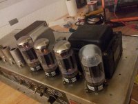
something wrong with #7, trying an old tube pair in #7 & 8.
now slight glow in all 4, equally looking by the two pairs.
switching new 7 & 8 with 9 & 10 , placing bad #7 in V10 socket.
noticing that the bad tube has much less "chrome" inside at the top, compared to the good 3.
power on:
slight glow in # 7,8 10 - not in 10
out of standby - same
(pic)
All 4 tubes are hot - not smoking hot, but too hot to hold - the 3 good ones a little hotter than the bad one - I consider this within normal.
Now something is happening in front of my eyes - the sorry remains of "chrome" inside the bad tube is changing from "chrome" to greyish color - it's being eaten from the inside.
I might as well stop here - this tube must be really hurt.
(pic)
The poor tube was really glowing when we testet last saturday, and apparently it was doomed then.
Maybe I can continue testing with a pair of old tubes together with a new pair, until a new tube arrives?
This would make for a different bias adjust, I assume...
very slight glow in #8,9 & 10 - not in 7
out of standby - same
power off, remove DBT, power on:
slight glow in #8, 9 & 10 - not in 7
out of standby - same
something wrong with #7, trying an old tube pair in #7 & 8.
now slight glow in all 4, equally looking by the two pairs.
switching new 7 & 8 with 9 & 10 , placing bad #7 in V10 socket.
noticing that the bad tube has much less "chrome" inside at the top, compared to the good 3.
power on:
slight glow in # 7,8 10 - not in 10
out of standby - same
(pic)
All 4 tubes are hot - not smoking hot, but too hot to hold - the 3 good ones a little hotter than the bad one - I consider this within normal.
Now something is happening in front of my eyes - the sorry remains of "chrome" inside the bad tube is changing from "chrome" to greyish color - it's being eaten from the inside.
I might as well stop here - this tube must be really hurt.
(pic)
The poor tube was really glowing when we testet last saturday, and apparently it was doomed then.
Maybe I can continue testing with a pair of old tubes together with a new pair, until a new tube arrives?
This would make for a different bias adjust, I assume...
Attachments

- Status
- Not open for further replies.
- Home
- Live Sound
- Instruments and Amps
- Fender PA100 - smoke -> no sound