One doubt many people have is if feedback isn't instantaneous, then how can it reduce distortions?
(BTW, feedback IS NOT instantaneous if there's some doubt about it).
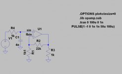
To show feedback in action, I've simulated the simple circuit below, with parameters taken from the well known Leach amplifier circuit (the amps' BW is 8 MHz).
(BTW, feedback IS NOT instantaneous if there's some doubt about it).
To show feedback in action, I've simulated the simple circuit below, with parameters taken from the well known Leach amplifier circuit (the amps' BW is 8 MHz).
Attachments
Input & feedback signals
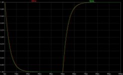
The figure below shows input signal (sin) in green, feedback (fbin) in red.
It's a 10kHz square wave, band limited to about 40kHz.
Just by looking at the figure, delay becomes aparent.
One can see there's a delay during the transition time (rise and fall) and it disapears when the signal is stable (flat top and bottom).
Attachments
Feedback error signal
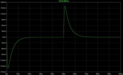
Here's the error signal (sin-fbin) applied to the amp to correct the error between input and output.
The error signal reaches 160mV at the beggining of the transition in less than 1 microsecond.
It is this large error signal that forces the amp to 'catch up' with the input, from there on the amplitude decreases until it falls to zero when the transistion has ended (flat top or bottom).
An amp with a wider BW will be faster (less time to catch up) and one with insuficient slew rate may distort because the error signal cannot rise fast enoug.
Are there negative aspects to this one microsecond delay?
I believe not, witness the many highly regarded feedback amps used all over...
Attachments
It's an obvious concern. I console my worries by the following train of thought.
Q1- What is the physical distance the feedback signal must travel?
A1- Well, in my board layouts it tends to be between 10mm and 50mm.
Q2- How fast does the feedback signal travel?
A2- I really don't know but it most certainly is some significant fraction of C.
Q3- For starters let's assume that the initial signal suffers no distortion. A delayed feedback signal will actually creat distortion. How significant is this?
A3- Well, suppose the feedback signal traves at 0.1C (probably way to small), or 30,000,000m/s. It will take 0.05/30,000,000 seconds to meet up with the original signal, that's 1.7 ns if I kept track of all the zeroes. It takes 50,000 ns to complete a full 360deg cycle of a 20kHz signal. 1.7/50,000*100= .003%. This is NOT a distortion figure; that would be much smaller.
Anyway, I'll relax and go back to sleep now.
Feedback cannot be 100% effective because it takes time for the audio signal to go through the amplifier.
Fortunately .... for audio frequencies, the delay through the amplifier is short enough to make inverse feedback work pretty well.
Fortunately .... for audio frequencies, the delay through the amplifier is short enough to make inverse feedback work pretty well.
Going back to my calculations, if they are approximately correct the difference between the actual delay and zero delay is so small the delay can be considered "virtually" non-existant. (For the microwave guys I can concieve that it is another matter entirely)
I really like the word "virtual" as in "virtual reality", or "virtually dead" (ref. M Python). I'm not quite sure what it really means but seems to be a servicable way of removing some of the knats in life's oinment.
I really like the word "virtual" as in "virtual reality", or "virtually dead" (ref. M Python). I'm not quite sure what it really means but seems to be a servicable way of removing some of the knats in life's oinment.
That's very interesting - I have never seen the actual time involved calculated or simulated. The interesting part is the error correction signal and the time scale. 1 usec is actually very slow - how can that be for a reasonably "fast" amplifier? The shape is horrendous too, I can imagine all sorts of bad things happening here...
1 usec is within the range of say, offset delay errors for speaker drivers (e.g. a tweeter offset of 5 mm to the woofer will have a delay of 1E6*0.005 m / 343 m = 14.6 usec. I would have thought electronics a lot faster than that.
BTW for all I know the delay is not related to the electron travelling time and speed and distance... It's the finite "reaction time" of the active devices, and reactive elements, creating group delay and phase shifts.
Will this bullsh%t about time delay ever stop?
Consider this:
Even in tube circuits, when electron flow at a relative inmensely slow speed through the tube semi vacuum from cathode to anode, still the time delays is of no concern for audio!
just because some japanse (chinese?) guys makes money of a 20$ chip amp that he sell for 2000$, doesn't mean that he rediculus theory about time delay and feedback is even remotely connect to any thrueth
PS
Q1: does a spice simulator actually take in to account the speed of electrical signals?...
Q2no? How can your simulatro then give any usefull info in this?
Speed of propagation of a field/signal in copper wire is C. The actual electrons however, only move at about 1cm per sec...
tschrama said:
Q1: does a spice simulator actually take in to account the speed of electrical signals?...
Q2no? How can your simulatro then give any usefull info in this?
If macro modeling of the feedback amp were used, it's possible to use the SPICE transmission line model somewhere inside the macro model. If the line were matched at both ends, that would simulate a constant delay independent of frequency.
"Will this bullsh%t about time delay ever stop?"
Probably not.
I have designed video DA's (distribution amplifiers) using Analog Devices AD-847JN chips.
I use inverse feedback in my design and they perform beautifully into the multi-MHz region.
Still .... Inverse feedback is not a cure-all. It works well when used to improve the performance of a well-designed amplifier.
The bottom line is this: If the amplifier sounds like h**l without inverse feedback, it will sound like h**l when you add feedback.
Get the design right and then use a little stage-by-stage feedback to make your design "shine".
Hi !
My expierience is, the really problematic thing about feedback is to
adjust the correct feedbackcompensation, not only to keep the amp
from oscillating, to avoid all forms of overshooting and ringing.
(Internal ringing, not visible at output)
But, 1us delay to rise to max slew is incredibly slow !
A very good amp is completely finished with slewing after 1us.
I remember ~50ns for this delay in sims, but have to recheck.
Anytime i "improved" feedbackbehaviour, the amp sounded better...
I have not found out yet what kind of distortions are caused by
"improper" feedback, but seems to be related to reactive loads.
The less gain an amp has, the easier it is to get this proper behaviour.
Mike
tschrama said:Will this bullsh%t about time delay ever stop?
Consider this:
Even in tube circuits, when electron flow at a relative inmensely slow speed through the tube semi vacuum from cathode to anode, still the time delays is of no concern for audio!
just because some japanse (chinese?) guys makes money of a 20$ chip amp that he sell for 2000$, doesn't mean that he rediculus theory about time delay and feedback is even remotely connect to any thrueth
PS
Q1: does a spice simulator actually take in to account the speed of electrical signals?...
Q2no? How can your simulatro then give any usefull info in this?
1 - There is no BS re time delay.
2 - I'm not aware of the guys selling snake oil. This posting is not related to them or they 'magic'.
3 - Not only does a Spice simulator takes in account the speed of electric signals, but in this very simple simulation it was taken in account.
It can give useful results because the amp has a pole at 80Hz (8MHz bandwidth and gain of 100k). This is the real signal delay.
Electron speed, etc has very little to do with feedback audio amps. The time to charge/discharge the compensating cap dominated the transient response.
MBK said:That's very interesting - I have never seen the actual time involved calculated or simulated. The interesting part is the error correction signal and the time scale. 1 usec is actually very slow - how can that be for a reasonably "fast" amplifier? The shape is horrendous too, I can imagine all sorts of bad things happening here...
My conceprual amp (posted in another thread) when submitted to the same signal has a delay of 100 nanoseconds (much wider bandwidth and more feedback gain).
And, believe one or not, no bad things are happening during the transient. After the inital rise, the feedback signal is just following the applied waveform (look at the second figure's slopes).
sam9 said:It's an obvious concern. I console my worries by the following train of thought.
Q1- What is the physical distance the feedback signal must travel?
A1- Well, in my board layouts it tends to be between 10mm and 50mm.
Q2- How fast does the feedback signal travel?
A2- I really don't know but it most certainly is some significant fraction of C.
if you go through the numbers, you will realize that you need the signal pass to be very very long (on the scale of thousands of miles) to be of a concern on audio signals.
Frank Berry said:The bottom line is this: If the amplifier sounds like h**l without inverse feedback, it will sound like h**l when you add feedback.
to me, the real bottom line is will the amp with feedback sound more or less like h**l than the original amp does.
All of the music signal coming from CD player is BW limited at 22kHz, that means about 17us rise time (10%-90%). The only quicker signal apparent at the amp input is EMI/RFI interference or DAC converter residuals. All of them no greater than milivolts or ten milivolts. Contemporary amp should have rise time no longer than hundreds of nanoseconds, that means 100 times faster than the steepest audio signal.
P.S.: it is a good practice to make an amp fast and to reduce bandwidth by input RC filter, so do not speak about feedback delay in this case please ....
P.S.: it is a good practice to make an amp fast and to reduce bandwidth by input RC filter, so do not speak about feedback delay in this case please ....
The "discoveries" shown here are well known to every engineer as a feedback basis, and should not be misinterpreted.
Anyway, nothing new. Search for articles about slew distortion and transient distortion from the early seventies.
Anyway, nothing new. Search for articles about slew distortion and transient distortion from the early seventies.
Re: Input & feedback signals
Congratulations, you have discovered phase shift in square waves after they pass through a system with a pole. 🙂
Jorge said:One can see there's a delay during the transition time (rise and fall) and it disapears when the signal is stable (flat top and bottom).
Congratulations, you have discovered phase shift in square waves after they pass through a system with a pole. 🙂
The error signal itself is not a problem unless the input stage is saturated, this causes slew distortion. The cure is BJT LTP emitter degeneration or JFET input stage. Or CFB amp.
- Status
- Not open for further replies.
- Home
- Amplifiers
- Solid State
- Feedback delay & distortion