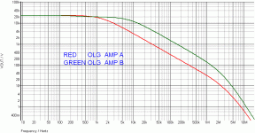
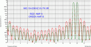
there is ~5.5 dB gain difference @20KHz - you are saying that explains the 30 dB change in 1 KHz IMD ?
the sim could tweak the GBW as well to get better than 1 dB match of 19,20 KHz
care to make a prediction about how much that would affect the results ?
the sim software is free
Even your schematic is simple, there s quite a big number of parameters
that are to be took account of.
I dont think that 5.5 db better loop gain at 20khz could explain
the 29db better figure , unless this is the increased loop gain of
a compensated amp wich would display nearby OLG at high frequency
by the virtue of a tighter NFB enclosing a local loop.
The local loop would then have better linearity , but then , the increased
GNFB + increased local NFB ratios should be equal to about 29db.
This is what transpired of my sims, that high freq. loop gain, or
slew rate, wich is the same in term of GBW product , must be increased
at the frequencies wich are intermodulating.
Feedback doesn't know or care where the unwanted output components originated. It only sees the amp input and output and compares them. It doesn't know that the 1kHz came from intermodulation, so it doesn't know how to 'correct' the intermodulation. It does know how to reduce 1kHz, because that is something in the output which is not in the input. It does the same for ripple, noise, interference etc. It even does the same for the input signal, which is why the gain is reduced too.
Agree on the principles, but then , if the 1Khz signal is to be corrected,
dont forget that it is made while the 19+20khz signal is present at the input.
Any action of the feedback loop that is too slow in respect of the signal
frequencies might as well increase the IMD products , and in fact , IMD
is partly due to lack of GB at the frequencies of interest.
It is the non linearity at 20khz that is producing this IMD , and to reduce
it , more linearity, i.e, more loop gain, at 20khz is necessary.
Last edited:
Lets do some more. The feedback reduces any signal at the output that is not present at the input,
Only if the feedback loop is fast enough , wich is precisely what is put
under question in my post....
No. Somewhere in the amp there is a box which has 19+20kHz going in, and 19+20+1+40kHz coming out. The feedback doesn't know and doesn't care whether this is due to distortion or because the box contains 1kHz and 39kHz oscillators. So lets swap the boxes over. Take out the distortion and put in the oscillators. Outside the box nothing has changed. Using what logic should we calculate the level of 1kHz by using the OLG at 20kHz? Clearly this is daft.
Thinking about feedback in terms of linearising transfer functions only works for flat systems, as I said. For real systems you need to treat each Fourier component separately.
Thinking about feedback in terms of linearising transfer functions only works for flat systems, as I said. For real systems you need to treat each Fourier component separately.
Last edited:
In case that the amplifier is fast enough, with slew rate high enough, and does not suffer from cross-conduction and cross-over distortion, then the CCIF IMD 19+20kHz is very similar in value to THD 1kHz at the same voltage swing.
clearly the OP has point of view that to many of us familiar with feedback, its enabling role in accurate amplification of audio signals disagree with
if we take the position that accuracy of amplification of the recorded music signal is the goal
the questions might include how was the asserted subjective observation made - controls, blinding, against what references, which examples of "feedback" vs "no feedback" amps...
then we have people jumping in with "confirming" tales of how "feedback" doesn't work...
...so is it a bad path to show where the "critics" are simply wrong about the theory, implementation, technology, limits of negative feedback?
Hello,
I have experienced that if you have big feedback and therefor low distortion you have lost good soundstage or imaging reproduction. I think the keyword is transients. I think feedback destroys the ability for transients.
The german test magazine Stereoplay I think current issue July 2011 shows an ampflifier without feedback but with another trick to lower distortion.
Does somebody know more about this amp?
What do you think, guys?
jcx,df96 your are correct about theory, I was self cheated by wahab reasoning, IMD pollution is about -70db (at audio, thanks to the NFB) in fairly good amps, shame on me
[snip]It is the non linearity at 20khz that is producing this IMD , and to reduce it , more linearity, i.e, more loop gain, at 20khz is necessary.
I believe you are lumping a few different things together.
To reduce the generation of IMD at 20kHz, you need more linearity at 20kHz, not loop gain. More loopgain at 20kHz (turned into feedback) would reduce anything at 20kHz that is not in the input signal. Clearly, the 19+20kHz signals are in the input so feedback doesn't decrease them.
To reduce the resulting 1kHz IMD product, you need loop gain turned into feedback at 1kHz.
jan didden
Last edited:
Only if the feedback loop is fast enough , wich is precisely what is put
under question in my post....
For practical purposes, the feedback is always fast enough - what's the signal delay through a power amp, less than a fraction of a microsecond?
You probably refer to phase shift in the amplifier path, which results in the phase of the fed back signal to be different to the input signal. Because of that, the 'cancellation' action of the feedback is incomplete so the distortion is not reduced to zero.
Since this phase shift increases with increasing frequency, the 'cancellation' gets less and less complete with rising frequency, and the distortion also rises with increasing frequency.
Now you may say that the rise of distortion with frequency is a result from less loopgain (and less feedback) with rising frequency, and that is true. But the less loopgain at higher frequencies is the result of the fall off of gain with frequency which is also responsible for the increased phase shift with frequency, so in a sense they are one and the same phenomenon.
jan didden
In case that the amplifier is fast enough, with slew rate high enough, and does not suffer from cross-conduction and cross-over distortion, then the CCIF IMD 19+20kHz is very similar in value to THD 1kHz at the same voltage swing.
Hi Pavel,
That is interesting. Is this an observation, or is there some technical reason why this would be the case?
jan didden
I believe you are lumping a few different things together.
To reduce the generation of IMD at 20kHz, you need more linearity at 20kHz, not loop gain.
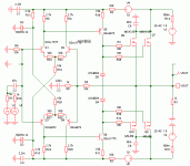
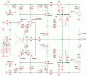
Here a practical exemple using a simple topology.
The amp B has its OLG increased at frequencies that are above
1khz , compared with the reference amp A wich display about the same
OLG at 1Khz but lower OLG at 20khz;
Since the amp A OLG is increased by reducing the emitter degeneration
of the VAS in AC mode using a capacitor, we can assume that lower
degeneration means less linear VAS.
The OLG figures shows that amp B has not a iota of gain increase at 1khz ,
but when looking at the IMD figures, what a surprise , the IMD product
at 1khz is reduced as well , even there s no increase in loop gain at 1khz.
So clearly , better linearity consequent to a higher OLG at 20khz has reduced
the low frequency unwanted by product of 19/20khz intermodulation.
Attachments
DF96,
Can the process of "straightening" and "suppressing" be described in terms of physics?There are two ways of thinking about feedback. Straightening the transfer characteristic, or suppressing frequency components. The former is only valid for flat open loop gain. The latter works for flat or frequency-dependent gain. NFB suppresses anything which is not in the input signal, including components generated by the mixing caused by NFB. The degree of suppression depends on gain at that frequency, not the frequency of whatever originally created the component.
Hi Pavel,
That is interesting. Is this an observation, or is there some technical reason why this would be the case?
jan didden
In case you restrict to electrical engineering only, no. In case you are educated in theory of human hearing and physiological acoustics, yes. IMO this (engineering point of view only) is the key of many misunderstandings.
For practical purposes, the feedback is always fast enough - what's the signal delay through a power amp, less than a fraction of a microsecond?
The following was stated from a 1978 documentation of Treshold amps by Nelson Pass :
Loop propagation time (propagation delay appearing at the bases of the input differential transistors)
400 A : 20 nS
800 A : 40 nS
Pass does not give details about the measuring procedure.
I drove my own tests on a Self power amp with no input filter, and integrated circuits TL074 and MC1458 set as voltage followers. Using a 10 kHz square wave of 20 nS rise time and a 100 MHz Scopemeter, one channel monitoring the input signal and the second channel monitoring the output signal (before the ouput self in the case of the power amp). I found these delays between the signal emerging from noise and the input signal :
Self amp : 50 nS
TL074 : 150 nS
MC1458 : 180 nS
In case you restrict to electrical engineering only, no. In case you are educated in theory of human hearing and physiological acoustics, yes. IMO this (engineering point of view only) is the key of many misunderstandings.
I think psychoacoustics come into play in questions like: are higher order distortion products masked by lower order ones? This is still a point of discussion, on which I hope through controlled listening tests an answer will be given. The reason is that this would give direction to subsequently engineering amplifiers that interface best - as in most agreable- with human hearing
The points made by Janneman and DF96 are just plain good old engineering issues as far as I can see. To push it a bit further: science and engineering have been key in settling many misunderstandings, often to the regret of those who see their errant believes overtaken by knowledge.
Some further note on using sim-results the way is done here. Sims are nice and useful, but sometimes rather inconsistent with real world results. For example, when designing active filters, a sim can give you a good sense of direction, but the real world piece of electronics always behaves differently.
Thanks.artu said:jcx,df96 your are correct about theory,
You are not comparing like with like. Increasing the OLG at 20KHz means that the signal in the early stages of the amp is smaller, so the non-linearity (e.g. in the LTP) has less effect. You are generating less 1kHz, not suppressing it better. Obviously, distortion depends on signal level. If it turned out that all the distortion was happening in the output stage then your circuit change would leave the 1kHz level unchanged.wahab said:Here a practical exemple using a simple topology.
So your circuit does show something interesting: a significant part of your distortion is being generated before the output stage. Given that the output is a follower this is not too surprising.
Last edited:
Wahab
Interesting AB comparison.
It seems to me that, at least in part, increasing the gain at 20Khz at the VAS results in less voltage swing (and distortion generation) at the input stage. I know this is obvious but its a slightly view as is being discussed, and at least shows the difficulty in trying to isolate effects to a single attribute.
DF96, sorry to double your post, was slowly drinking my first coffee.
Thanks
-Antonio
Last edited:
But you was talking about measured , objective results, so what they have to do with psychoacustics and human hearing??..In case you restrict to electrical engineering only, no. In case you are educated in theory of human hearing and physiological acoustics, yes. IMO this (engineering point of view only) is the key of many misunderstandings.
This is valid only if OLG linearity is "suboptimal", e.g. by loading VAS in order to obtain flat OLG to 20kHz and more (PIM??)In case that the amplifier is fast enough, with slew rate high enough, and does not suffer from cross-conduction and cross-over distortion, then the CCIF IMD 19+20kHz is very similar in value to THD 1kHz at the same voltage swing.
In case you restrict to electrical engineering only, no. In case you are educated in theory of human hearing and physiological acoustics, yes. IMO this (engineering point of view only) is the key of many misunderstandings.
Pavel I think you misunderstand my question, which was directed to your statement that the CCIF IMD at 1kHz (from the 19+20kHz input) would be at the same level as the 1kHz THD. I don't see any link to hearing etc in that. Am I misisng something?
jan didden
- Status
- Not open for further replies.
- Home
- Amplifiers
- Solid State
- Feedback affects Soundstage, Imaging, Transients ?


