Hi elder brother
hello Rajeev paaji
Oh brother yaar mere naal naraaz tan nahi hogaye.
chote brother kolo je koi galti hoyee hove tan maaf kar deo.
Oh bhai gal es tara hai ke mein bahut busy hega wa, you know in other project till 30th april.
mein apna design jaroor devan ga but you have to wait for a very little while.
changa phir , raji khushi raho,
kanwar
amplifierguru,
Please give me the link to your work you are mentioning .
K- Amps,
I have checked it is 2A at 60v , I will be bridiging both the channels ie that is 11pairs per channel , total 22pairs of devices , it is very safe now
Ampman ,
Thanks for your offer , since last five months you say you are sending your pcb , I think I can manage of my own , however you had promised others of your great design on this thread , you better please all .
hello paaji
oh paaji yaar you know i am very busy thats why there is a delay of my design and pcb.
stay cool and have a nice sweet dreams at night
kanwar
rajeev luthra said:Thanks for your offer , since last five months you say you are sending your pcb , I think I can manage of my own , however you had promised others of your great design on this thread , you better please all .
oh paaji yaar you know i am very busy thats why there is a delay of my design and pcb.
stay cool and have a nice sweet dreams at night
kanwar
Hi Rajeev,
The Eidetic amplifier I mentioned was a 1990 design, now just a collectors item.
Instead of a 50-0-50 secondary I used a transformer with 4 x25V windings so these would be connected to the bridge as either 50-0-50 for 70V rails, OR FOR LOW IMPEDANCE loads the rear plug reconfigured the windings for 25-0-25 at twice the current giving 35V rails. Simple - so the amplifier was 150W/225W for 8/4 ohms and similar for 1/2 ohms all from a 300VA transformer!
Thanks
But I do not think that will be useful in pro use and switching transformer tappings at high currents, also my requirement is mostly of max power . Any further sugestions are welcome .
But I do not think that will be useful in pro use and switching transformer tappings at high currents, also my requirement is mostly of max power . Any further sugestions are welcome .
amplifierguru said:Hi Rajeev,
The Eidetic amplifier I mentioned was a 1990 design, now just a collectors item.
Instead of a 50-0-50 secondary I used a transformer with 4 x25V windings so these would be connected to the bridge as either 50-0-50 for 70V rails, OR FOR LOW IMPEDANCE loads the rear plug reconfigured the windings for 25-0-25 at twice the current giving 35V rails. Simple - so the amplifier was 150W/225W for 8/4 ohms and similar for 1/2 ohms all from a 300VA transformer!
Guru,
I am assuming that the 2x currents sucked out during 2/1 ohm operation were.... well.... not life threatening for the Toroid.
K-Amps
I did my calculations again ,
You are RIGHT ,
With 11 pairs of 2SC5200/2SA1943 I can get max 730w at 1 ohm ie
1460w in bridge ( 2 channels ) at 2 ohms within SOAR , 40-0-40v
transformer and this is not my requirement ,
The only way it can be of my use is to get 700w per channel at 4 ohms
with imp matching transformers in output .
Hence I will take your advise and call mjl 21193/4or 95/96
or MJ21193/94or95/96 .
Another thought is to change the output stage to N-Channel and use
IRFP250 mosfets .
Thanks for saving my amp from unreliability ,
Rajeev
PS,
I checked the price of MJ21193 it is $2 each , howcome it is lesser than
mjl 21193 ?
TO-3's are less in demand than TO-3PL's.
By the way at 80v the 95/96 are better, at 100v, the 21193/94 are better....
So now what design are you going with?
By the way at 80v the 95/96 are better, at 100v, the 21193/94 are better....
So now what design are you going with?
K-amps,
paralled windings delivered twice the current at half the voltage. Same load for the primary. So no difference in load on the transformer, but the halved supply rails allowed doubled currents from the MOSFET output stage.
paralled windings delivered twice the current at half the voltage. Same load for the primary. So no difference in load on the transformer, but the halved supply rails allowed doubled currents from the MOSFET output stage.
OK I thought you were tying the primaries in series to half voltage... seems like a more elaborate switching of the secondaries.... Pretty high current connections on the fly eh? I hope it's corrosion proof. 😉
Hi,
I would not recommend changing the voltage on the fly!!
When the speaker load is changed then the voltage change is made.
low volts setting for 2 or less ohm.
high volt setting for 4 or more ohm.
I would not recommend changing the voltage on the fly!!
When the speaker load is changed then the voltage change is made.
low volts setting for 2 or less ohm.
high volt setting for 4 or more ohm.
K-Amps,
Oh , I got carried away trying to utilise the Toshibas , there is no sence
reducing the supply voltages , at lower voltages I have better choice of
transistors with higher current capacity.
1st option,
I will make the same amp only I will go back to what I had in mind eirlear ,
+/-87v rails, I can go up a little only as caps are 100v, and max power
possible upto 2 ohms . ( what power do you think I will get )
I will change the heat sink and use 8 to 10 pairs MJ21193/94 or 11
pairs MJL4281A/MJL4302A which have very good gain ( as you
recommend ), same pcb , as the TO-3 transistors will be mounted
directly on the heatsinks the collectors I will be automatically connected ,
I will only have wire the emitter and base to the pcb for each TR ,
fortunately that also suits the existing pcb layout .
I will make one channel in one chasis so that I can make a heavy 1350va
transformer and get more output with powerful rails , I also have to look
at portability of the amp , for two channels I will either have to
compromise on the output power or make a very bulky 3000va
transformer increasing the size and weight ..
2nd option,
The second option that I have is to modify the output stage and use the
easily availible IRFP250 availible here ,
3rd option,
Buy readymade class D modules
What do you recomend ?
Cheers
Rajeev
PS ,
For choice 1&3 I will have to call material from the US as the same are
not availible here .
It depends on ...........
Hi Rajeev,
Your final option depends on your need.
If you need to have it all done properly, reliably and quickly, maybe you should pick the third option. It also has the advantage that the digital amp module will be more efficient and smaller and lighter and ( the circuit ) would be tried and tested.
Building the large amp from scratch is a very satisfying but time consuming option. If you have no serious time frame , then building it will be fun .
So maybe option 3 should be on top of the list if you are very concerned about time.
The thread however has been very interesting and useful.
Cheers,
Ashok.
AndrewT said:Hi,
I would not recommend changing the voltage on the fly!!
When the speaker load is changed then the voltage change is made.
low volts setting for 2 or less ohm.
high volt setting for 4 or more ohm.
Tell that to Ampguru 😉 , I am not too comfortable tying secondaries in parallel either.....
Rajeev,
It's your call. Since you have assembled parts and PCB for the TO-3PL... go with that. If I were you, I'd keep the design as is and use MJL21193/94 or MJ21193/94 as u like.
If you were going for hi-fi I'd suggest he MJL4302 etc but in pro audio you need reliability and the 21193/94 are VERY reliable and robust devices. PS Audio uses them in their power generators where a constant 60Hz sinewave is produced to power components. That requires the most rugged devices at high voltages. Unlike Music which has a smaller duty cycle than a constant 60Hz sinewave to produce 120VAC (in a bridged arrangement).
Paul McGowan (founder PS Audio) shared this info... he said they used +/- 105vdc rails..... I asked him why they didnt use c5200/ a1943, and he said the 21194/94 were much more robust. You tell me how many amplifiers have you seen with a straight emitter follower design (not TOTEM pole) that had 105volt rails and ran such heavy duty?
For Pro audio, hi rails and reliability.... not many BJT's come close to the 21193/94.
You can later on scale up the voltages and add more devices. If need be.
Hi,
Yes I too feel that the final option is MJ21193/94 , I will call the same from you .
But until then I am once again going to try out using IRFP250 they are costing equal to $1.00 here , the specks are also good , 190w , 200v, SOA 2.5A at 220v WOW
Yes I too feel that the final option is MJ21193/94 , I will call the same from you .
But until then I am once again going to try out using IRFP250 they are costing equal to $1.00 here , the specks are also good , 190w , 200v, SOA 2.5A at 220v WOW
Hi elder brother
Hi Rajeev,
I think now you are very much impressed with the N-channel Mosfets regarding to SOA, thats why you WOW.😉
cheers
Kanwar
rajeev luthra said:Hi,
Yes I too feel that the final option is MJ21193/94 , I will call the same from you .
But until then I am once again going to try out using IRFP250 they are costing equal to $1.00 here , the specks are also good , 190w , 200v, SOA 2.5A at 220v WOW
Hi Rajeev,
I think now you are very much impressed with the N-channel Mosfets regarding to SOA, thats why you WOW.😉
cheers
Kanwar
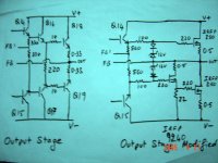
This is what I did last night , I modified the output stage from current
driven to voltage driven so that I could use IRFP250 mosfets in the output
of the same amp , the rails to the rest of the amp will be higher both
sides than that of the output stage .
Some additions can be done like grounding two 33k resistors from the
base of the bases of Q14 & Q15 to load the driver stage , take output
for the mosfets from the emitters of Q16 & Q17 and increase the
value220 ohm resistor a little,. instead from the emitters of Q14 & Q15
The schematic of the output stage is attached ,
Let me know if this is ok.
Rajeev
K-Amps
200v is minimum it is actually higher , also 2.5A at 1ms
Attachments
- Status
- Not open for further replies.
- Home
- Amplifiers
- Solid State
- Favorite High Power Output Transistor