Bits and pieces..............
OK I think there is a lot of confusion because we are talking only about bits of the subject in different posts.
Jens and K-amps have it right. We are talking about average dissipated power. Note that each transistor dissipates power only for one half of the ac waveform (which it is amplifying).
Max heat dissipation is also at about 1/3 of max output.
No simple calculation for max power output is exact as there are other factors to consider. Supply capacitor voltage drop and Vce saturation voltage and other internal circuit losses also determine maximum power output capability.
Approximations are OK as they get us to a ballpark figure quickly.
Hi Jacco,
I'm thinking nothing. The calculation is only to show the figure arrived at is incorrect as the 40% refers to heat lost and 60% goes to the load. 100% comes from the power supply. I was not thinking of what goes where and why.
I think I have the heat lost calculations right and don't want to get into an argument with anyone about that. Everyone can believe what seems right to them. I find the text books right - theoretically speaking !
Cheers.
Re: Bits and pieces..............
Yes max dissipation occurs at approximate 1/3rd power factor.
One thing to note is that while each device contributes to the half AC cycle (actually more in class-AB) we can NEVER exceed each device's max rating at ANY point whether half cycle or not.
So for calculating the number of devices needed, each device's sec breakdown parameters should never be exceeded. Once we achive that, the next step (calculating total dissipation for thermal deration) can use some kind of averaging algorithm but ONLY after the former has been accurately sized.
What I do not want Rajeev to think is that he can size his output stage based on "averages" otherwise at some point of the sinewave, he will exceed the SOAR and send his Toshiba's to the great BJT heaven up there.
My responses are more for Rajeev to make sure he sizes his OP stage correctly and not about the Theory involved... don't really care to join a contest of textbooks here... they are boring. 😉
ashok said:
Jens and K-amps have it right. We are talking about average dissipated power. Note that each transistor dissipates power only for one half of the ac waveform (which it is amplifying).
Max heat dissipation is also at about 1/3 of max output.
Cheers.
Yes max dissipation occurs at approximate 1/3rd power factor.
One thing to note is that while each device contributes to the half AC cycle (actually more in class-AB) we can NEVER exceed each device's max rating at ANY point whether half cycle or not.
So for calculating the number of devices needed, each device's sec breakdown parameters should never be exceeded. Once we achive that, the next step (calculating total dissipation for thermal deration) can use some kind of averaging algorithm but ONLY after the former has been accurately sized.
What I do not want Rajeev to think is that he can size his output stage based on "averages" otherwise at some point of the sinewave, he will exceed the SOAR and send his Toshiba's to the great BJT heaven up there.
My responses are more for Rajeev to make sure he sizes his OP stage correctly and not about the Theory involved... don't really care to join a contest of textbooks here... they are boring. 😉
Re: Re: Bits and pieces..............
Same here, sorry K-master.
K-amps said:My responses are more for Rajeev to make sure he sizes his OP stage correctly and not about the Theory involved... don't really care to join a contest of textbooks here... they are boring.
Same here, sorry K-master.
Re: Re: Re: Bits and pieces..............
Hey Jacco, just for the record, you are of the rare breed that contribute on this forum to help people, some others do it for their ego... so hats off to your type. ;-)
jacco vermeulen said:
Same here, sorry K-master.
Hey Jacco, just for the record, you are of the rare breed that contribute on this forum to help people, some others do it for their ego... so hats off to your type. ;-)
11 devices thermal + SOAR
Hey Rajeev
At idle your power supply has 87 volt rails and under full power with say a 1500va to 2000va transformer your power supply will drop to about 80 volts RMS. This assumes a mono amplifier.
80 volts - 8v (across transistors) * 0.707 = 51 volts RMS
51 volts across 4 ohms = 650 watts RMS at best.
51 volts across 2 ohms = 1300 watts RMS at best.
The maximum dissipation across the output stage occurs at about 60% of maximum output. So for 2 ohms this will be 1300 watts x 40% = 520 watts. Add to this the idle bias current i.e. 50 mA per transistor pair = 550mA x 174 volts = 95 watts.
520 watts + 95 watts = 615 watts divided by 22 transistors = 28 watts per transistor. To be safe lets make it 30 watts. At a junction temperature of 100° C the transistor can still dissipate 60 watts of instantaneous power so everything is ok from a thermal point of view. No problems here.
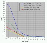
Now to estimate the SOAR. I have presented the 2 and 1.5 ohm resistive load lines plus the 100ms SOAR of 11 devices in the attached graph. The curve for devices at 25° C is well above the 1.5 ohm load line but unfortunately the derated 100ms curve gets very close and this means that if your heatsinks get warmer than about 70° C there is too little margin to assure safety. Remember that the actual impedance is complex and the load seen by the amplifier could dip even lower.
For general music applications (but not musical instrument) 11 devices should be ok and I would be quite comfortable using this amp. With a sine wave at full power for a few seconds the output stage would probably die, but this never happens with general music.
Hopes this helps
Cheers,
Hey Rajeev
At idle your power supply has 87 volt rails and under full power with say a 1500va to 2000va transformer your power supply will drop to about 80 volts RMS. This assumes a mono amplifier.
80 volts - 8v (across transistors) * 0.707 = 51 volts RMS
51 volts across 4 ohms = 650 watts RMS at best.
51 volts across 2 ohms = 1300 watts RMS at best.
The maximum dissipation across the output stage occurs at about 60% of maximum output. So for 2 ohms this will be 1300 watts x 40% = 520 watts. Add to this the idle bias current i.e. 50 mA per transistor pair = 550mA x 174 volts = 95 watts.
520 watts + 95 watts = 615 watts divided by 22 transistors = 28 watts per transistor. To be safe lets make it 30 watts. At a junction temperature of 100° C the transistor can still dissipate 60 watts of instantaneous power so everything is ok from a thermal point of view. No problems here.
Now to estimate the SOAR. I have presented the 2 and 1.5 ohm resistive load lines plus the 100ms SOAR of 11 devices in the attached graph. The curve for devices at 25° C is well above the 1.5 ohm load line but unfortunately the derated 100ms curve gets very close and this means that if your heatsinks get warmer than about 70° C there is too little margin to assure safety. Remember that the actual impedance is complex and the load seen by the amplifier could dip even lower.
For general music applications (but not musical instrument) 11 devices should be ok and I would be quite comfortable using this amp. With a sine wave at full power for a few seconds the output stage would probably die, but this never happens with general music.
Hopes this helps
Cheers,
Attachments
Hi Quasi,
"Add to this the idle bias current i.e. 50 mA per transistor pair = 550mA x 174 volts = 95 watts."
Just a thought here, this calc assumes that the idle current is flowing through the pair of transistors all the time. In a classAB amp the driving transistor increases it's current while the partner decreases and eventually swithes off. In a low bias design the switch off will occur close to zero volts (100mA into 8R=0.8V).
this effectively means that the idle bias is flowing for only slightly more than 50% of the cycle. I would like to suggest that when driving a heavy load the total dissipation in your example is 520w +0.5*95w =568w
Comments please.
in following para you said "At a junction temperature of 100° C the transistor can still dissipate 60 watts". Did you mean Tc of 100degC?
Hi Quasi,
What happens to the loadline if the amp plays into a reactive load?
Does this change anything?
\Jens
What happens to the loadline if the amp plays into a reactive load?
Does this change anything?
\Jens
Hey AndrewT
My answer contains a few assumptions.
I chose to use the constant 50mA per device beacuse this is what the output stage will be doing most of the the time i.e. nothing, even during music and in between music. So from an average point of view the idle power dissipation is valid. But as you say in practice it will vary.
I did mean junction temperature as this is how the transistor is derated for SOAR, hence my reference to instantaneous power instead of average power. A transistor with a case at 25 deg C could still have a junction temperature way above that during peaks.
Cheers
Ha Ha ...you see why I specified resitive load.
Yes Jens, everything changes.
Hopefully with a nominal 2 ohm load there will be enough resistance in the emmitter resistors and speaker cable to save the amp ha ha ha ha ...sheeesh. Umm Rajeev better add a couple of pairs. Then again we are only talking about music and not RMS.
Cheers
JensRasmussen said:Hi Quasi,
What happens to the loadline if the amp plays into a reactive load?
Does this change anything?
\Jens
Yes Jens, everything changes.
Hopefully with a nominal 2 ohm load there will be enough resistance in the emmitter resistors and speaker cable to save the amp ha ha ha ha ...sheeesh. Umm Rajeev better add a couple of pairs.
Then again we are only talking about music and not RMS.Cheers
Have a look at this page
http://www.sound.westhost.com/soa.htm
My calculation show what Rod already simulated.....
You MUST be sure what happens when the amp is loaded with reactive loads.... The case Rod uses is not at all unlikely, and the transistors will die if it exceeds the SOA, even if it is for only a short time.
I have not finished my calc. yet, but I will post them when they are done.
You have to look at two cases:
1) The maximum dissapation in the output stage (at Vout= 0.64*Vrail) for calculating the temperature on the heatsink and transistor junction
2) The maximum peak dissapation at reactive loads that must be within the derated SOA for the transistor at all times.
Only when both cases are examined and approved, will the amp be ok for PA use.
In domestic amps the designer sometimes cut corners to lower the cost of the amp.
\Jens
Jacco,
1, I would like to make it clear that the max amb tem in my city will never
be above 35digrees near the amp ( Ampmans temp conditions do not
apply here ), next please note that I am mounting the devices on the
heatsink directly without any insulator for max heat transfer , I am using
extra large heatsinks wt 2.7 kg with 4" cooling fan at full speed for one
channel . As required by you I will post the the °C/W / cm figures of
heatsink as soon as I get them from the manufacturer . Like this I hope to
keep the device temp as low as possible .
2, I am using 5200/1943 devices as they are the only good devices
availible here at a reasonable price .
3, You are right by saying
" Seems you desire to build an amplifier that needs to survive the worst
climate at the highest operation voltage, and you wish minimum
impedance operation. "
at least I am trying .
4, How can I get max power from these devices safely anyhow .
K-Amps recomends the max power I can get from a 5200/1943 device
is .
"A ball park 70v rail will yield a max of 77 watts per device from a
5200/1943 device. (Based on the SOA, 1.1 amps @ 70v) 11 pairs is
about 1700 watts max. Take away 25% for non-resistive loads and you
are left with 1270 watts of useable power. "
Now regarding the idea in my head ,
I can also utilise the highest power capacity of the devices at lower
supply voltages , and get my required loudspeaker imp ( which will be 2
ohms or 4 ohms ) by adding a autotransformer in the output , I have done
it in another amp and it works well ( this was done in the Makintosh
make amps many years ago ),
I have no problem in making my choice matching transformer having
custom input/output impedance and wattage , transformer size will also
be small as an auto transformer need be only of the power that is added
for increasing output voltage ,
like this I can get my desired output voltage without increasing the rails .
I hope now you can give me an estimate of how much 11 pairs can
handle.
Quasi,
Thanks for all the trouble , in fact I would like to thank everyone for their
contribution .
I will be using the amp in pro use ( music only NOT sine wave ) and here
it is mostly used at high output levels hence I can get away with quesent
current of 10 to 20 ma per transistor , also I am trying to give it good
cooling , as written to Jacco above . Now by reading all this would you
like to add anything to your eirlear reply .
Regards
Rajeev
Rajeev,
Too many variables, Quasi made calculations based on 3-4kVa transformer for both channels hence rails sagging from 87 to 80vdc.
I assumed 1kva transformer shared by both channels. In this scenario, I estimate your rails drop to 70vdc under 2 ohm operation or 75vdc under 4 ohm operation or 78 under 8 ohm operation.
You need to let us know the regulation and size of transformer for any calculations to be representative of what you want.
K-
Jans View ?
Hi Jan
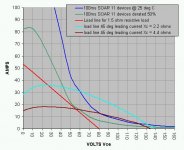
I think this is what you are talking about. The graph below shows a scenario of current leading voltage by 45 degrees in reactive loads with Xc's of 2.2 ohms and 4.4 ohms.
Even with a nominal 4 ohm speaker and Tj of 25 degrees 11 pairs may not be enough because the 100mS SOAR will be exceeded under certain signal conditions. So this means that 2 ohms for 11 devices is definately out but 4 ohms should be ok for general music.
Sorry Rajeev for misleading you earlier. Got any spare FETS to make this problem go away?
Cheers
Hi Jan
I think this is what you are talking about. The graph below shows a scenario of current leading voltage by 45 degrees in reactive loads with Xc's of 2.2 ohms and 4.4 ohms.
Even with a nominal 4 ohm speaker and Tj of 25 degrees 11 pairs may not be enough because the 100mS SOAR will be exceeded under certain signal conditions. So this means that 2 ohms for 11 devices is definately out but 4 ohms should be ok for general music.
Sorry Rajeev for misleading you earlier. Got any spare FETS to make this problem go away?
Cheers
Attachments
K- Amps,
Yes the rails will drop as you have predicted by writing the following ;
" if you begin with 87vdc rails unloaded (and 70vdc at full load including
losses etc ) that will give you about 49.49volts RMS into 8 ohms or about
300 watts RMS. At 4 ohms depending on the PSu regulation, you can
get 500 watts, @ 2 ohms about 850 watts and at 1 ohm about 1400
watts. So the Max you can get from 11 pairs of TOS devices is around
1400 watts."
Further you say;
"If you wanted max power at 8 and 4 ohms, I'd jack up the rails but then
would never use it at 2 ohms."
But what I mean is that instead of jaking up the rail voltage I add an auto
transformer in the output to get my required output at 4 ohms and 2ohms
, 8ohms is NOT required . Like this I can take maximum advantage of
the SOA .
Now I tell you why I am after all this , it is because I am making an amp
for my custom requirement and want to utilise it fully , I rarely see pro
sound operators getting their requirements from commercial amps
easily , and thus have to go for overrated amps .
Quasi ,
You have taken into account rail drop to 80v at full load but it will be
much lesser , somewhere near what K-Amps predicts that is 70v. Now
the whole scenereo changes .
It is ok if I cannot go down to 2ohms output but , I want 800w at 4 ohms and without increasing the rails or lowering the rails and adding the auto transformer seems to be the only solution other than bridging .
Jens very rightly writes;
"You have to look at two cases:
1) The maximum dissapation in the output stage (at Vout= 0.64*Vrail) for
calculating the temperature on the heatsink and transistor junction
2) The maximum peak dissapation at reactive loads that must be within
the derated SOA for the transistor at all times.
Only when both cases are examined and approved, will the amp be ok
for PA use."
Two things that come to mind regarding your design goals:
1) Paralelling transistors may not be the best policy to avoid SOA limitations in your case. Due to the shape of the SOA curve, you may gain from connecting the devices in series, though this complicates the drivers somewhat. Motorola / Onsemi has an application note that uses this approach in a power amp. It was actually even referenced on this forum a while ago.
2) While on the topic of series connected output transistors - just one step further you get class G operation (rail switching). In your case this should be a serious consideration, which not only makes SOA issues MUCH less problematic, but also may save you some money on heatsinks, as well as potentially make the amp more robust re overheating. You could also use MOSFETs for the power rail switching, which they are eminently suitable for. At the same time they can be used for protection circuitry. If you do not like class G operation, you could use some more exotic topologies such as MOSFET/BJT cascoded outputs (again, SOA issues are largely avoided, while the output stage retains largely BJT-like character.
ilimzn said:Two things that come to mind regarding your design goals:
1) Paralelling transistors may not be the best policy to avoid SOA limitations in your case. Due to the shape of the SOA curve, you may gain from connecting the devices in series, though this complicates the drivers somewhat. Motorola / Onsemi has an application note that uses this approach in a power amp. It was actually even referenced on this forum a while ago.
2) While on the topic of series connected output transistors - just one step further you get class G operation (rail switching). In your case this should be a serious consideration, which not only makes SOA issues MUCH less problematic, but also may save you some money on heatsinks, as well as potentially make the amp more robust re overheating. You could also use MOSFETs for the power rail switching, which they are eminently suitable for. At the same time they can be used for protection circuitry. If you do not like class G operation, you could use some more exotic topologies such as MOSFET/BJT cascoded outputs (again, SOA issues are largely avoided, while the output stage retains largely BJT-like character.
He already has his PCB made out and components placed etc....
Rajeev,
An autotransformer will waste 10-20% power as well as affect the sound.
If that is not a consideration and you want to maximise the power, then go with 50v rails (loaded) i.e. 60v unloaded.
At 50vce, each 5200/1943 can give you your full 150 watts per device max, i.e. 3 amps at 50v.
22 devices is 3300 watts. Less 25% for reactive loads (estimate)
Gets you close to 2500 watts capability. Thermally derated, a ball park of 1500 watts per channel is not too unrealistic.
With 50 v rails (assumes loaded plus losses) you can get 35.35vac RMS which is about 156 watts 8 ohms, 312 watts 4 ohms, 625 watts 2 ohms and 1250 watts 1 ohm.
At 1 ohm, you will be pulling about 35.35 AMPS from the Output stage. Where as it can safely source a max of 33 amps steady, hopefully your rails will drop under 1 ohm load and increase the SOAR.
With 60v unloaded (50vdc loaded) rails, i am ver sure you can get over 1000 watts no problems.
With your Auto former set at a ratio of 1:2, with an 8 ohms load, you will get about 500 watts RMS (assuming a 10% power loss) and about 1000 watts at 4 ohms.
K-
PS: Your power Toroid better be capable of handling such high current densities 😉
Thanks everybody ,
Now I have the following choice ,
1, reduce rails to 70v (50-0-50 transformer), the rails on load should be
around 60v or lower ? and bridge the amp and I will get around 2000w at
2 ohms , this suits me .
2, reduce rails to 70v again and add a auto transformer in output and get
up to 1000w / ch at X ohms as per my requirement , or reduce to 56v (
40-0-40v transformer) and get 1500w / ch with autotransformer .
3,call mjl 21195/6 from the US , a little difficult , also calling replacements
later could be a problem,
Finally the no 1 option seems to be the best . I hope this will be final .
K-Amps ,
do you give me the green signal now??
Next what to do with the 66-0-66v transformer and 100v caps , I can
make another amp , IRFp250N mosfets are availible very cheap here ,
Mr Holton is using 10 pairs of IRFp240/9240 complementry mosfets and
getting 1000w , I hope I can modify the output stage of the leach amp
and make it N-channel with your help and use the availible IRFp250N s
or make The Zeeta ( I wonder why no one claims to have made the
1000w version of the Zeeta inspite of over 8000 people having
downloaded the schematics . )
Have you considered doing what I did in the Eidetic(TM) power amplifier which was to have a transformer with 4 equal secondary windings and switch to series or parallel pairs of windings for either the 4/8 ohm HIGH impedance load or 1/2 ohm LOW impedance loads by halving the supply rails. This then gives similar power levels for 1/2 ohm as for 4/8 ohm and better utilizes the SOAR.
I used an user selectable octal plug in the back panel to either series or parallel pairs of windings. Worked a treat.
I used an user selectable octal plug in the back panel to either series or parallel pairs of windings. Worked a treat.
Rajeev,
The max SOAR occurs at 50v not 60v. So you need to begin with 60-63 v unloaded to get 50v loaded. Bridged this will give you about 1300 watts into 4 ohms or 2400 watts into 1 ohm if your power supply can provide 35 amps. To me that would be a 3.5kVa transformer !
70 uloaded (60v) loaded will reduce the SOAR significantly....
- Status
- Not open for further replies.
- Home
- Amplifiers
- Solid State
- Favorite High Power Output Transistor