I am looking for a completed mini amp with "auto-on" to use in my shed for my backyard system and stumbled up on this amp at Parts Express. In the Q&A section they say this amp uses class D topology with a TDA8932T at its heart. Just wondering if any of you have any experience with this amp.
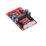
Dayton Audio DA30 2 x 15W Class D Bridgeable Mini Amplifier
Dayton Audio DA30 2 x 15W Class D Bridgeable Mini Amplifier
Below is an interesting read.Don't see the apt-x there.
https://www.cnet.com/news/can-aptx-give-you-better-sound-over-bluetooth/
I have a Samsung tablet with apt-x and an apt-x receiver board, you need both, and I do not notice any improvement over BT4 products.
I originally wanted this chip board for making a mono mini bluetooth speaker (with a 5" 2way driver), but recently discovered that there already are boards with bluetooth built in ready to go, which is fantastic and make things more easy.
Whats bad is that there are no mono boards. So i was wondering if is it possible wiring a single speaker into the L-R terminals and so getting mono sound? just like when you mix signal sources. 😕

Whats bad is that there are no mono boards. So i was wondering if is it possible wiring a single speaker into the L-R terminals and so getting mono sound? just like when you mix signal sources. 😕
Attachments
So i was wondering if is it possible wiring a single speaker into the L-R terminals and so getting mono sound? just like when you mix signal sources. 😕
That is not the right way to mix two channels of a stereo system.
But..
But you may use either of the two channels from this Board and leave the other channel unused (I don't see any harm there)
For Conversion of Stereo to Mono,you need to add a stereo mixer.
Whats bad is that there are no mono boards. So i was wondering if is it possible wiring a single speaker into the L-R terminals and so getting mono sound? just like when you mix signal sources.
For mono btl config of the chip:
Look at Fig. 35 & 36 of the datasheet.
You will find a way to modify your board to mono btl.
For mono signal input:
Look at the traces between the bluetooth part and the chip input.
Identify the signal paths of the L and R channel.
Put a resistor of ~10K into each signal path of the two channels.
Then you will be able to tie the channels together after the resistor and before the chip input.
(...just google how to sum the signal and apply it to your board.)
Parallel. . . to raise the impedance of my speakers I use output transformers and this cleans up the highs nicely. . . I'd definitely not recommend car speakers with TDA8932 as they tend to be rather low impedance (due to cars having low voltage supplies).
I wonder if this chip, or its bigger brothers, have ever been used in Parallel mode? Looks odd; however, it will run cooler and with the inputs + to + and - to -, this chip and its bigger brothers won't fuzz. Also a parallel amp is a much simpler, less bulky and less expensive way to get a more favorable output impedance for the amplifiers (since each sees half the load). The physical size of the thermal interface would be more favorable as a parallel amp, probably resulting in full capacity available. Given two such parallel amplifiers (sync'd), adding the base stopper resistors at input and an external bridge adapter, then a full power, full quality bridge amp, becomes a possibility.
It seems that the missing piece to the puzzle, is a good parallel amp?
Do anyone have a suggestion to what active X-over to use with these fantastic amps..? Preferably a DIY style board, as I need to fit it into an active speaker.
@Daniel: Can you post a schematic of the diodes you use when having more than one amp per PSU?
@Daniel: Can you post a schematic of the diodes you use when having more than one amp per PSU?
I don't have a schematic handy. But it is this:Do anyone have a suggestion to what active X-over to use with these fantastic amps..? Preferably a DIY style board, as I need to fit it into an active speaker.
@Daniel: Can you post a schematic of the diodes you use when having more than one amp per PSU?
SMPS > cable> capacitance > high-current low-voltage diode series to V+ > amp.
Each amplifier board has its own diode.
For that application, check the diode's datasheet and choose one with a current vs voltage drop graph that looks like "|" not "/". You want that graph to look like a straight up wall (throughout the applicable range of current).
Then, the inherent CRC filtering action doesn't dump your bass like a resistor would do.
So, at least 6a capacity and not greater than 200v tolerance. And, as many diodes are there are amplifier boards.
Mainly, this will let you have your one SMPS, and then a cable, drive one cap bank, to power several amplifiers, without crosstalk.
Within the range of 0.55v to 0.8v fvdrop, the effectiveness and power costs are both constrained to a tiny amount; however, in my opinion and personal usage, hearing less power supply influence was worth the cost of two fat diodes.
P.S.
This is not relevant to using a 3-wire (sensor lead goes all the way to load) SMPS with a monobloc, so long as additional reservoir capacitance wasn't added. That is a rare case. But, it will neither harm nor help that case. The CRC effect from this mod, which a Class AB amp would nearly lick your boots for, is not needed by the amp on this thread. So, the effectiveness, if any, is removing the negative consequences of adding a high capacitance reservoir and removing multi-channel crosstalk. That's not much help, but the price is also not much.
P.P.S.
I do not use active crossovers due to the caveats in working small signal op-amps appropriately (the manufacturer not likely to do that) and the fact that altering speaker dampening is more convenient when done directly, at large signal, with passive parts. Neither the convenience nor the price differ significantly; however, the speaker level parts in a real crossover have absolutely no opportunity to degrade the quality of small signal before there is a lot of gain applied to that by the amplifier. And, then there's the problem that small signal equalizers and related technology (active crossovers) are the level worst thing to do for current management tasks. I'm never doing that. There are both voltage and current adjustments available; but, the one thing is not good at the other's job.
Okay, I do have some digital active crossovers available; however, I just use them for room correction and nitpicks, but never to replace a real crossover. The tasks are quite different and we need to use the parts that are most effective for the given tasks.
Had it gone the other way around, then distortion would be maximized, and I wouldn't want to do that on accident.
For sure, there are a very few speaker drivers made, with such a flat response per each that the needful adjustment is within the range of an active crossover to get the job done without excessive distortion; but, that is a rare case, and it costs more.
To apply an active crossover without excessive distortion, the signal must be digital all the way to the active crossover AND the active crossover settings must not be excessive in trying to do what a passive should have been doing. In other words, no big fell swoops at small signal modifications.
Making een super liniair triangle with a dsp or other cpu can make distortions low, without feedback, a digital made triangle is can be precise .
regards
regards
Hello everyone, who I can 'say the best among tda8932 x 2 or tda 8932 bluetooth powered by a 13.8V 5A Microset ip 5212 8 ohms 87db 3-way speakers.
Hello everyone, who I can 'say the best among tda8932 x 2 or tda 8932 bluetooth powered by a 13.8V 5A Microset ip 5212 8 ohms 87db 3-way speakers.
Please do elaborate on that and document at bit.
Thanks.
Hello, I was wondering which was the best among the tda8932 or tda3982 bluetooth, powered by a 13.8V 5A stabilized power supply "microset ip 5212" with 8 ohms 3-way speakers "RCF BR 45". Thanks for the help.
Hello, I was wondering which was the best among the tda8932 or tda3982 bluetooth, powered by a 13.8V 5A stabilized power supply "microset ip 5212" with 8 ohms 3-way speakers "RCF BR 45". Thanks for the help.
With large speakers, you might want to increase/parallel the size of the speaker level dc block caps provided on the board.
It has a higher power voltage tolerance, if you wanted more output power.

With 8 ohms, you could use the higher voltage range, or with 4 ohms, you could use the lower voltage range.
With 24v, you'd want 8 ohm speakers.
With 24v, you'd want 8 ohm speakers.
Still really love this amp. Specifically, those cheap bridge boards set to SE mode (or split rail). I'm using it bi-amp, in mixed mode, which has the rather efficient tweeter utilizing SE mode, while the woofer utilizes bridge mode. That's have your cake and eat it too.
Hi, can you post an schematic how to convert the board to SE mode for bi-amp? ThanksStill really love this amp. Specifically, those cheap bridge boards set to SE mode (or split rail). I'm using it bi-amp, in mixed mode, which has the rather efficient tweeter utilizing SE mode, while the woofer utilizes bridge mode. That's have your cake and eat it too.
Sent from my ONE A2001 using Tapatalk
Hello, I'm still waiting for a bluetooth TDA8932 card, even though more than a month has passed and I doubt it will arrive anymore. Anyway, I had planned to buy 2 TDA8932 cards, so I'd like to ask an opinion to Daniel. Is it better a TDA8932 or a modified TDA7297? Thanks for the answer.
Still really love this amp. Specifically, those cheap bridge boards set to SE mode (or split rail). I'm using it bi-amp, in mixed mode, which has the rather efficient tweeter utilizing SE mode, while the woofer utilizes bridge mode. That's have your cake and eat it too.
Hi,
Can you post a schematic or a picture on how to convert board to SE.
Thanks
- Home
- Amplifiers
- Class D
- Fasten seat belts. TDA8932 pessimistic review.