Alright, made a new drawing
Your line is not taking advantage of driver offset that helps minimize the 1st undesirable line harmonic which allows for less damping which in the ends gets you more bass reinforcement.
Otherwise looks like a nice design.
dave
That first clip sounds fantastic!
Thanks! It is surprisingly good aounding for $32 worth of drivers and a few foam core sheets. The miniDSP makes it possible. If I packaged this as a conventional prismatic box it would indeed make a nice bookshelf speaker that I could live with for a long time.
Dave: I can still move the bass driver down the line as the driver holes are not pre-drilled. However, I wonder if the sound will be more uniform if they are closer together?

36 square feet of 24mm BB ply sawed to measurements for 100 dollars. Not a bad price, at least by Finlands standards 😀
36 square feet of 24mm BB ply sawed to measurements for 100 dollars. Not a bad price, at least by Finlands standards 😀
Attachments
I love it when a plan comes in motion. That's the best part for me. Looking at all the planks cut and knowing what it will become in a near future!
For a 400 Hz XO, you can have the full range and bass driver separated by about 12 inches and it should be fine. That doesn't buy you much. XO at 250Hz and you can go to 18in. You can also keep driver closer and add a real 180 deg fold at the top. But your boards are cut already...
It's a very good price. 🙂
How far you can slide the woofer down the line depends mostly on your crossover point. As this is a FAST, and the crossover will be low, there is some wiggle room. The general rule of thumb is 1/3 wavelength, though some will say 1/2wl, and 1/4wl is better if feasible. Basically it will lobe if they are too far away. This must be balance against the increased smoothness you will achieve with an offset driver.
How far you can slide the woofer down the line depends mostly on your crossover point. As this is a FAST, and the crossover will be low, there is some wiggle room. The general rule of thumb is 1/3 wavelength, though some will say 1/2wl, and 1/4wl is better if feasible. Basically it will lobe if they are too far away. This must be balance against the increased smoothness you will achieve with an offset driver.
Of course this rule is broken all the time, like by every little HT sub/satellite system out there...
True, plus other considerations are driver/floor eigenmodes and driver/LP 'floor bounce' frequencies..........
GM
GM
I can still move the bass driver down the line as the driver holes are not pre-drilled. However, I wonder if the sound will be more uniform if they are closer together?
MJK in his tables suggests a driver offset of 0.326
Drivers closer togther means you can XO higher and still have them within a 1/4 wavelength at the XO.
dave
Does he have a newer set in a different doc than the one in his 10.20.06 rev. Classic TL doc, which doesn't list a 0.326? http://www.quarter-wave.com/TLs/Alignment_Tables.pdf
GM
GM
I guess there was a reason the one one i found on my HD was called old 🙂
The one you linked says 0.336
dave
The one you linked says 0.336
dave
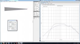
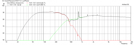
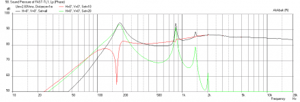
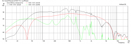
I simulated the 3 options. To my untrained eye, the driver 1/5 down the line would seem best in this application. The 1/3 down the line is too low considering the distance from FR driver unless I lower the XO point.
Attachments
Last edited:
Given the reality of the enclosure and the fact that it isn't a hypothetical tapered cylinder with a perfect flat end, I think three decimal places of precision is a bit optimistic...
Anyhow, if it were mine, I would probably choose the ~1/3L placement for the woofer over closer placement to the TC9FD. Having a big null at ~130-200Hz. can really take away from the subjective weight and enjoyability of the music, and an offset driver is the easiest way to get rid of it. OTOH, I and many others built successful end loaded TL before accurate sims were available. With careful attention to stuffing, etc, problems can be minimized. You may want to try in 1/5L placement in your software also, as a compromise. (10"/25.4cm offset)
EDIT: Oh, you beat me to it. Yeah, 1/5 looks pretty good.
GM makes a good point about floor bounce and eigenmodes. These are very real effects and should be considered.
I would pick the 1/3 option for the increased bandwidth. You don't want the XO to be below 200Hz - it starts taxing the TC9FD on excursion and reduces the midrange clarity. Also for reasons GregB gave about weight of mid bass in the 80 to 200Hz region is where a lot of impact comes from.
Seems like I have a choice between rock and a hard place. What would happen if I used two bass drivers, one at 1/3, and one for example in 1/5? I would try to model this, but Leonard Audio software only supports one driver location.
I can model this in Akabak pretty easily with multi drivers. Get me your drawn to scale sketch of the profile and driver locations. If you put the drivers at 1/5 and 1/3 they are quite close together and can be approxinated as dual drivers at the mid point between 1/5 and 1/3. Also, if you provide the dimensions of the short TL for the top as well as cabinet width and driver locations son baffle I can model the whole system response with XO and baffle step and diffraction. Also indicate how far away your back wall is and that reflection will also be included.
Last edited:
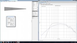
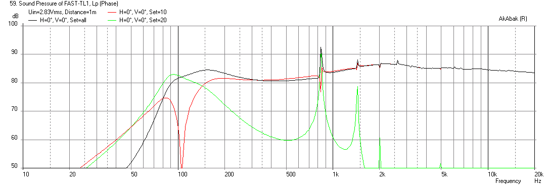
FWIW, this is the quick & dirty line as I designed it in post 4, complete with horrific response problems caused by the 1/10 tap location insufficiently supressing the pipe harmonics.
It was there to allow closer placement between the drivers. Personally, I didn't think it was such a bad compromise, but YMMV as always of course.
It was there to allow closer placement between the drivers. Personally, I didn't think it was such a bad compromise, but YMMV as always of course.
Attachments
Here's a link to the image in pretty big resolution: http://i.imgur.com/R6x6e6A.jpg
The TC9 line lenght from center to end is 300mm. All widths are 270mm. If you want, could you also simulate one driver at 440mm from top, 345mm from line center (the topmost bass driver) alone. It's pretty much as far as I could go from the full range without issues. Back wall will be about 330mm away from from baffle edges. The edges will be rounded, but I doubt it can be simulated for. Last, but not least, the line lenght is about 131cm.
Thanks in advance!
EDIT: I have only faint clues on how drivers should be placed on baffle. Maybe bass drivers on middle, full range about 30mm from one side? It gave the best result on EDGE simulator.
Last edited:
Simulation of FAST TL
Using the geometry of the design from your earlier post: http://i.imgur.com/R6x6e6A.jpg
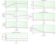
I modeled it in Akabak. The main bass TL is quite good with two drivers - nice sensitivity of 91dB at 2.83v, a smooth response with an f3 of 55Hz and smooth rolloff like a pro audio speaker:
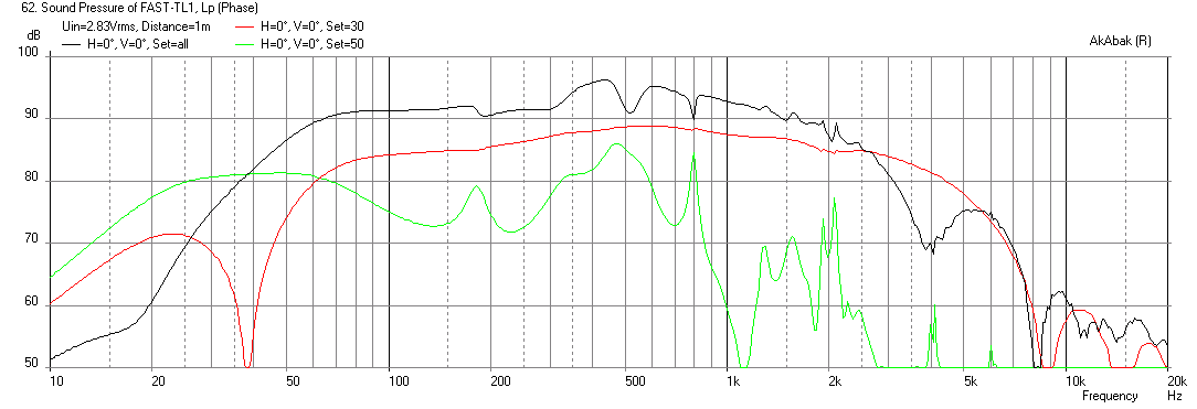
The HF TL however has a pronounced peak with a 10mm terminus, which does not give a very smooth XO:
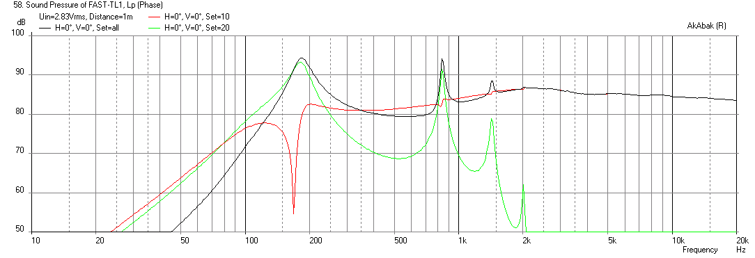
If we reduced the terminus to 1.3mm, it is much better:
Here is the combined response of the bass TL and the HF TL using a 300Hz -24dB LPF for the bass and a 370Hz -24dB HPF for the top:
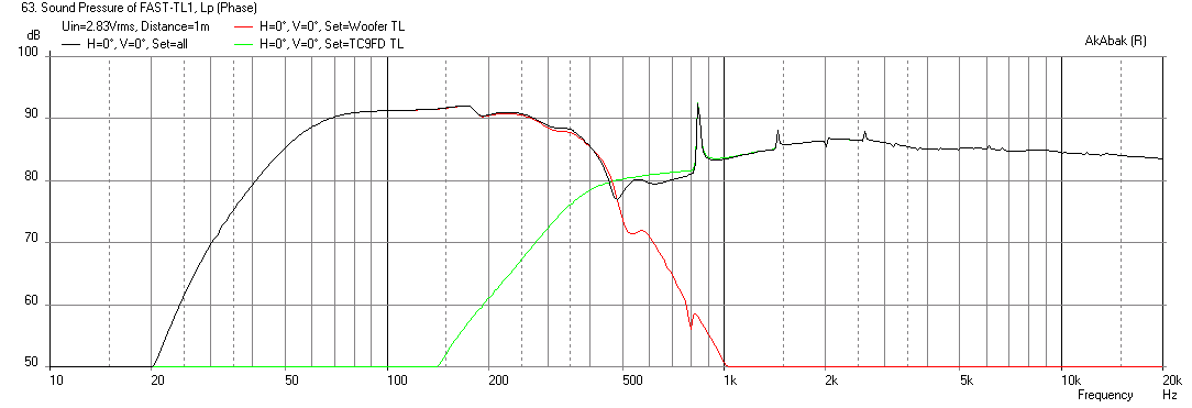
As you can see, the sensitivity of the woofers overwhelms the TC9FD, you would need to run it at 4x the voltage to compensate and that is not good. Alternatively, a 91dB sensitive driver like the Faital Pro may work better here.
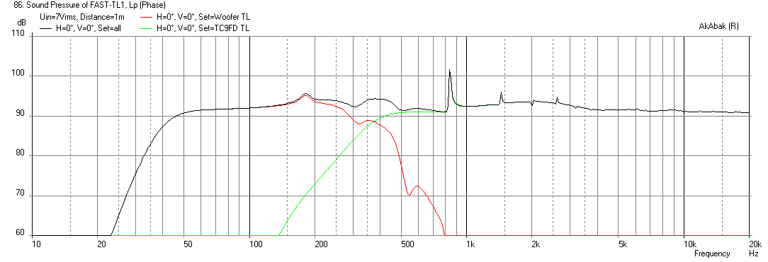
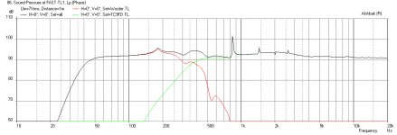
The simpler way is to run the bass TL with only a single driver, the volume has doubled so the tuning will drop lower and the f3 is at 41Hz. The TC9FD now requires 1.6x gain relative to the the woofer, and a BSC circuit using a 0.8mH coil and a 6ohm resistor to level the response:
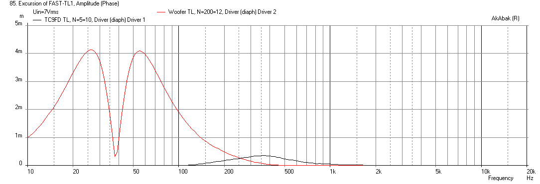
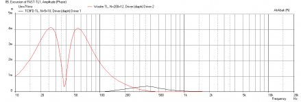
The problem with this driver in a TL like this is that the cone motion control is not very good, as 4 mm of xmax is reached at only 7 volts drive on the woofer - this really limits your max SPL levels:
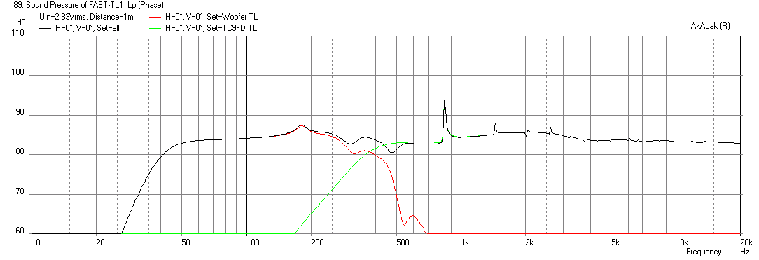
Here is the frequency response at 2.83v drive on the single woofer:
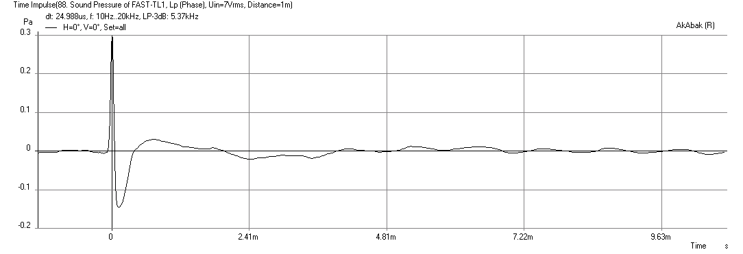
Here is the impulse response, quite nice:
So in summary, I think the major findings are:
1. Use a single woofer if you want get closer to balanced levels with the TC9FD (still needs 1.6x boost)
2. Use a 300Hz -24dB/oct LPF for the woofer and 370Hz -24dB/oct HPF for the fullrange
3. Make the terminus gap on the top TL 1.3mm vs 10mm
Using the geometry of the design from your earlier post: http://i.imgur.com/R6x6e6A.jpg
I modeled it in Akabak. The main bass TL is quite good with two drivers - nice sensitivity of 91dB at 2.83v, a smooth response with an f3 of 55Hz and smooth rolloff like a pro audio speaker:
The HF TL however has a pronounced peak with a 10mm terminus, which does not give a very smooth XO:
If we reduced the terminus to 1.3mm, it is much better:
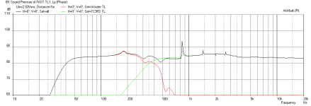
Here is the combined response of the bass TL and the HF TL using a 300Hz -24dB LPF for the bass and a 370Hz -24dB HPF for the top:
As you can see, the sensitivity of the woofers overwhelms the TC9FD, you would need to run it at 4x the voltage to compensate and that is not good. Alternatively, a 91dB sensitive driver like the Faital Pro may work better here.
The simpler way is to run the bass TL with only a single driver, the volume has doubled so the tuning will drop lower and the f3 is at 41Hz. The TC9FD now requires 1.6x gain relative to the the woofer, and a BSC circuit using a 0.8mH coil and a 6ohm resistor to level the response:
The problem with this driver in a TL like this is that the cone motion control is not very good, as 4 mm of xmax is reached at only 7 volts drive on the woofer - this really limits your max SPL levels:
Here is the frequency response at 2.83v drive on the single woofer:
Here is the impulse response, quite nice:
So in summary, I think the major findings are:
1. Use a single woofer if you want get closer to balanced levels with the TC9FD (still needs 1.6x boost)
2. Use a 300Hz -24dB/oct LPF for the woofer and 370Hz -24dB/oct HPF for the fullrange
3. Make the terminus gap on the top TL 1.3mm vs 10mm
Attachments
-
 FAST-TL1-1.6x-TC9FD-with-BSC-and-single-TC18WG49-Combined-Impulse.png15.3 KB · Views: 786
 -
 FAST-TL1-1.6x-TC9FD-with-BSC-and-single-TC18WG49-Combined-at-2.83V.png29.4 KB · Views: 769
 -
 FAST-TL1-1.6x-TC9FD-with-BSC-and-single-TC18WG49-Combined-Displacement.png29.7 KB · Views: 869
 -
 FAST-TL1-1.6x-TC9FD-with-BSC-and-single-TC18WG49-Combined.png30 KB · Views: 1,471
 -
 FAST-TL1-TC9FD-and-TC18WG49-Combined.png30.6 KB · Views: 775
 -
 FAST-TL1-TC9FD-Only-1.3mm-terminus.png17.8 KB · Views: 1,200
 -
 FAST-TL1-TC9FD-Only-10mm-terminus.png33.4 KB · Views: 871
 -
 FAST-TL1-dual-TC18WG49-Only.png34.6 KB · Views: 818
Last edited:
1. The maximum SPL isn't really desirable in this build, as my friends lives in an apartment building. Listening will be done at moderate volumes. The thought of using two drivers is a nice one, but ordering the faital pro driver would break the budget set by my friend.
2. Interesting points. As I'm planning on using PLLXO (budget constraints), the maximum would be 2nd order with Q of about 0.5. It's interesting that this is actually cheaper to do as an active build than passive as the big chokes for low-frequency crossover cost a fortune.
3. Good tip on the full range TLs terminus, it's easier to make smaller by just adjusting the angle of the board separating the TLs. Why does it need baffle step though?
What kind of damping did you simulate in these? By default, I was thinking of lining all internal walls with 8mm felt and build up from there if necessary.
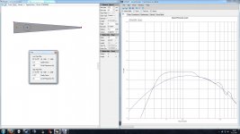
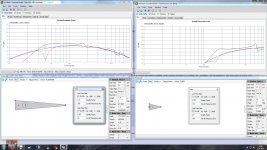
EDIT: The shortfall of this Leonard Audio software is that it can only simulate one instance per time. So, had to run two instances to get both drivers along. Here's my take on the 1/5th down the bass TL line for simulation.

2. Interesting points. As I'm planning on using PLLXO (budget constraints), the maximum would be 2nd order with Q of about 0.5. It's interesting that this is actually cheaper to do as an active build than passive as the big chokes for low-frequency crossover cost a fortune.
3. Good tip on the full range TLs terminus, it's easier to make smaller by just adjusting the angle of the board separating the TLs. Why does it need baffle step though?
What kind of damping did you simulate in these? By default, I was thinking of lining all internal walls with 8mm felt and build up from there if necessary.
EDIT: The shortfall of this Leonard Audio software is that it can only simulate one instance per time. So, had to run two instances to get both drivers along. Here's my take on the 1/5th down the bass TL line for simulation.
Attachments
Last edited:
- Status
- Not open for further replies.
- Home
- Loudspeakers
- Full Range
- FAST with TL?