I used moderate damping from closed end to just where driver ends on bass TL and along full length on small TL. Damping equal to a pressure drop of 7500 Pa/m^2 per m. Similar to filling with polyfill.
Baffle step happens due to finite width of baffle on full range driver. Can't be avoided unless you are wall mounted or have a bipole driver.
On PLLXO, there may be a way to do 24dB/oct if you use a powerful preamp buffer driver. I think sonething like a 4 ch headphone amp may work.
Baffle step happens due to finite width of baffle on full range driver. Can't be avoided unless you are wall mounted or have a bipole driver.
On PLLXO, there may be a way to do 24dB/oct if you use a powerful preamp buffer driver. I think sonething like a 4 ch headphone amp may work.
Hmm, need to look into the 24db/oct PLLXO. Currently I'm considering this approach:
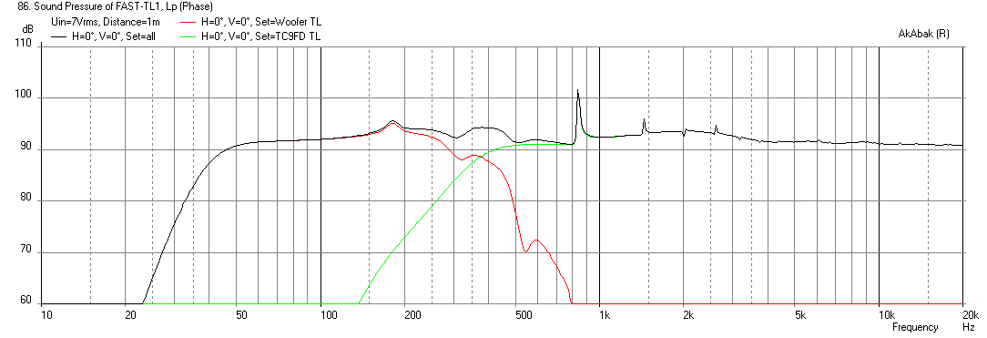
Bass driver 25cm down the line (see above post for frequency response) for smooth 200-300Hz roll-off. 2nd order (Q~0.5) lowpass on 350Hz. Bass driver in vertically on the middle of baffle. Bass driver is more efficient, so it will be matched to full ranges maximum level.
Full range driver at the end of the line (no other place for it to go), also centered vertically. 1st order highpass and PLL baffle step build according to Baffle Step Compensation instructions. Response simulated on EDGE shows that it has slight peak at 0,5kHz -1,6KHz area, but this should compensate for the TL design losses (see attached picture). No need for full 6db compensation as it's not an echoless chamber, probably 3db will be enough.
Of course all this will change as I get the speakers together and start measuring them 😀
Attachments
Sounds like a good plan. The bass TL is a nice result to get 41Hz extension that is smooth out XO is not a bad outcome at all. You will be happy with the TC9FD on top - another choice is open baffle for the top and TC9FD works well there too. A 12in wide baffle will have natural 350 Hz falloff as XO point.
Shouldn't OB have a bit more space in behind them? Remember, these will be placed right next to a wall, so distance from baffle edge to wall would be only about 330mm.
Shouldn't OB have a bit more space in behind them? Remember, these will be placed right next to a wall, so distance from baffle edge to wall would be only about 330mm.
Oh, forgot about that, OB needs at least 4 ft so fuggedaboutit.
As you can see, the sensitivity of the woofers overwhelms the TC9FD, you would need to run it at 4x the voltage to compensate and that is not good. Alternatively, a 91dB sensitive driver like the Faital Pro may work better here.
Given the 4x difference, what about a series connection?
Hmm, need to look into the 24db/oct PLLXO. Currently I'm considering this approach:
Bass driver 25cm down the line (see above post for frequency response) for smooth 200-300Hz roll-off. 2nd order (Q~0.5) lowpass on 350Hz. Bass driver in vertically on the middle of baffle. Bass driver is more efficient, so it will be matched to full ranges maximum level.
Full range driver at the end of the line (no other place for it to go), also centered vertically. 1st order highpass and PLL baffle step build according to Baffle Step Compensation instructions. Response simulated on EDGE shows that it has slight peak at 0,5kHz -1,6KHz area, but this should compensate for the TL design losses (see attached picture). No need for full 6db compensation as it's not an echoless chamber, probably 3db will be enough.
Of course all this will change as I get the speakers together and start measuring them 😀
How wide is your baffle? Obviously, you won't need baffle step compensation if the crossover point is the baffle step, assuming you have the requisite difference in efficiency between the woofer the the TC8FD.
OK then, so it already is at the crossover - around 350hz.
In this case I don't understand why BSC is being proposed for the mid/hi driver?
In this case I don't understand why BSC is being proposed for the mid/hi driver?
OK then, so it already is at the crossover - around 350hz.
In this case I don't understand why BSC is being proposed for the mid/hi driver?
The model shows that there is a falloff from about 1.5kHz to 2kHz down which I assume is baffle step.
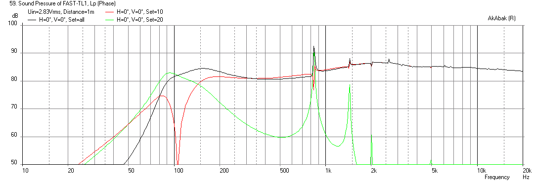
Applying the 0.8mH parallel 6R gives a flatter response:
Hmm, if the baffle width is 320mm, using the usual (John Murphy) baffle step formula
F3 = 115/W (W = width in meters)
gives an F3 of 359Hz.
EDGE or whatever might provide something more precise, but usually this formula is pretty good. The little Vifa might have rising response or something, but that's too high for the dip to be due to baffle loss.
The filter does correct the response however, whatever the cause. Alternatively, the crossover could be overlapped.
The rising response would be driver specific and not show up in Akabak based on T/S params alone. Maybe it is some sort of midrange enhancement from the TL? I see it in real measurement - this rise at 1.5kHz.
Hmm, need to look into the 24db/oct PLLXO.
The only way to do that is to buffer the filter stages, and then it isno longer a PLLXO
2nd order (Q~0.5) lowpass
A 2nd order PLLXO may have a lower Q than that.
dave
Mayuri good luck the building process.
Should budget allow down the road a more flexible XO here some EU retailers.
MiniDSP in box at 105€ Blue planet acoustic | OmnesAudio MiniDSP 2x4 Boxed | Lautsprecherselbstbau.
A Behringer 24dB LR analog stereo two way XO at 81€ Behringer CX2310 SuperX Pro - Thomann Suomi.
Should budget allow down the road a more flexible XO here some EU retailers.
MiniDSP in box at 105€ Blue planet acoustic | OmnesAudio MiniDSP 2x4 Boxed | Lautsprecherselbstbau.
A Behringer 24dB LR analog stereo two way XO at 81€ Behringer CX2310 SuperX Pro - Thomann Suomi.
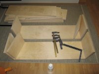
Looking good Mayuri. 😀
To answer one of your earlier questions about alignment: I prefer to keep the drivers in a vertical line, offset slightly towards the inside edge of the box. Perhaps this is sort of an old school approach, but it works.
To answer one of your earlier questions about alignment: I prefer to keep the drivers in a vertical line, offset slightly towards the inside edge of the box. Perhaps this is sort of an old school approach, but it works.
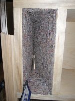
Nice work! I like how you use the wood sliver to control the TL exit gap. You might want to add polyfill stuffing in there too.
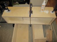
Beautiful cuts and attention to detail.
Beautiful cuts and attention to detail.
- Status
- Not open for further replies.
- Home
- Loudspeakers
- Full Range
- FAST with TL?