Christer said:Eva,
I agree one should be careful interpreting the simulation results. When I did simulations on this I was mainly interested in the qualitative behaviour, that is, whether such a phenomenon could be provoked at all in a simulation, since it was claimed to exist in reality.
Chris:
You've seen this before, problem is that I can't find the reference in my notebooks to the actual transformer I used, although I am pretty sure that the diode was an MUR860:
An externally hosted image should be here but it was not working when we last tested it.
I think that these pictures contribute to prove that ringing in 50Hz power supplies is not related to diode reverse recovery but just to transformer leakage inductance resonating with diode capacitance, and all diodes have capacitances, particularly schottky ones (altough they tend to be more constant than in conventional diodes).
Note that diode capacitance varies a lot with instantaneous reverse-bias voltage and this may constitute by itself a good high frequency ringing triggering signal.
Concerning snubbers, knowing the ringing frequency F when no snubber is connected, there is a basic rule of thumb that states that the relationship between C and R should be F = 1 / (R*C). So damping ringing in a somewhat optimum way is just a matter of finding the biggest R and smallest C capable of producing reasonable ringing suppresion while satisfiying that formula. At least, it works quite well for SMPS.
Also, one of the things that you learn about ringing when working with SMPS is that the wrong values of snubber R and C may boost ringing sometimes instead of just damping it, so choosing component values randomly is not a good idea at all. (Why audio people is so hesitant to just take an oscilloscope and look at what is actually happening inside their circuits??)
... becuase rather many hasn't got the equipment and/or aren't very interested. It's sufficient if it "sounds good".Eva said:(Why audio people is so hesitant to just take an oscilloscope and look at what is actually happening inside their circuits??)
Or because people who claim there are RF problems from reverse recovery also say it takes RF equipemnt to measure it and it cannot be seen on a scope. Whether they are right, I don't know, but at least this makes it a bit pointless to even try. I did once, failing to see anything on my scope, although some people seem to have succeeded. If I remeber correctly, Till once posted some scope pictures that showed a very different ringing pattern than Jacks, so he succeded to capture something.
These captures were taken from the power supply of an actual audio amplifier while playing loud music. The transformer is made with a big EI core that I scrapped from an old B/W TV set from 1960s and whose secondaries I rewound to match my needs. There are two diode bridges, one for each rail, and they are conventional KBPC2506-like (actually old FAGOR FB2506 from 1980s), those big ones with square shape and fast-on connectors. There are two 10.000uF 63V filter capacitors connected in paralell for each rail.
Red trace shows transformer secondary current measured with a 0.022ohm non-inductive resistor soldered directly to the diode bridge terminals, the trace actually shows the voltage drop across the resistor, so each 0.022V are 1 A. Blue trace shows voltage waveform at the diode bridge terminals. The time base and volts/div scale of each capture are shown in its header.
I think that the pictures are rather self explaining, they show a lot of facts abut 50Hz power supplies and about diode behaviour, like:
- The very high peak to average ratio of the current waveform.
- How the diode current rises and falls gradually.
- How the diode behaves when it's "asked" to stop conducting while driven from a highly inductive source (the downslope after the glitch).
- Some 200Khz ringing, altough the currents involved are negligible.
These details are hardly seen on any simulator. Enjoy it.
Red trace shows transformer secondary current measured with a 0.022ohm non-inductive resistor soldered directly to the diode bridge terminals, the trace actually shows the voltage drop across the resistor, so each 0.022V are 1 A. Blue trace shows voltage waveform at the diode bridge terminals. The time base and volts/div scale of each capture are shown in its header.
An externally hosted image should be here but it was not working when we last tested it.
An externally hosted image should be here but it was not working when we last tested it.
An externally hosted image should be here but it was not working when we last tested it.
An externally hosted image should be here but it was not working when we last tested it.
An externally hosted image should be here but it was not working when we last tested it.
An externally hosted image should be here but it was not working when we last tested it.
An externally hosted image should be here but it was not working when we last tested it.
I think that the pictures are rather self explaining, they show a lot of facts abut 50Hz power supplies and about diode behaviour, like:
- The very high peak to average ratio of the current waveform.
- How the diode current rises and falls gradually.
- How the diode behaves when it's "asked" to stop conducting while driven from a highly inductive source (the downslope after the glitch).
- Some 200Khz ringing, altough the currents involved are negligible.
These details are hardly seen on any simulator. Enjoy it.
Eva:
Don't want you to do all the work again -- but did you look at the data when the amp was just idling, or just above the point where the diodes are conducting --
the other thing to try is examining the traces with a low power device (i.e. preamp) where R(Load) is some tens of milliamps.
Jack
Don't want you to do all the work again -- but did you look at the data when the amp was just idling, or just above the point where the diodes are conducting --
the other thing to try is examining the traces with a low power device (i.e. preamp) where R(Load) is some tens of milliamps.
Jack
The amplifier was playing loud music, I have already mentioned it. Furthermore, each capture was done exactly during the period of increased current consumption that follows each bass transient. All captures were done almost at the same peak pulse current level.
I also observed the behaviour of the system as volume was increased starting from idle. The magnitude of the overshoot just when te diode turns off appears to be quite proportional to the peak pulse current. However, the number of times that it rings appears to be constant with load, and the current fall slope when the diode is "asked" to stop conducting is also constant, it does not change with load, it appears to be related only to mains waveform voltage slope, and the leakage inductance of the transformer (plus mains distribution network leakage inductance itself!!!).
I have made more captures. The two first ones show what happens when the amplifier is muted (bias removed). The three last ones show what happens when the amplifier is idle (biased but with no signal applied).
It's obious that things get better as load current is reduced. Concerning the noise that appears on the current trace, it's picked up RF from ambient, it doesn't change at all when the amplifier is phisically disconnected from mains, and it disappears if I short the probe. In this age of movile phones and wireless ADSL internet access it's quite easy to pick remarkable amounts of RF with a small loop antenna.
An externally hosted image should be here but it was not working when we last tested it.
An externally hosted image should be here but it was not working when we last tested it.
An externally hosted image should be here but it was not working when we last tested it.
An externally hosted image should be here but it was not working when we last tested it.
An externally hosted image should be here but it was not working when we last tested it.
This pic is quite close what i saw on scope when measuring that second transformer, oscillations just attenuated bit slower in my tests.Eva said:
An externally hosted image should be here but it was not working when we last tested it.
- The very high peak to average ratio of the current waveform.
- How the diode current rises and falls gradually.
- How the diode behaves when it's "asked" to stop conducting while driven from a highly inductive source (the downslope after the glitch).
- Some 200Khz ringing, altough the currents involved are negligible.
These details are hardly seen on any simulator. Enjoy it.
BTW. I got almost identical looking waveforms on spice as they were in my real-word measurements, just add 100k resistor over diode so that it is not ringing forever like in Heinz sims.
It is interesting to note, though, that Hagerman, who seems to be considered the authority on snubber calculations (at least on this forum) uses Spice simulations to demonstrate the effect of snubbers and his simulations show turn-off ringing of the type that powerbeckers simulations showed (and that I recall from my own simulations too).
www.hagtech.com/pdf/snubber.pdf
www.hagtech.com/pdf/snubber.pdf
The following captures were taken in the same cconditions as the ones from my first post, at more or less the same peak pulse current level and exactly the same circuit.
Some of you may be wondering what happens if a 100nF 100V capacitor is paralelled to the AC terminals of the diode bridge... Well, thiese two captures show the result :
As it can be seen, the high frequency current transient is almost supressed, but the 200Khz ringing is still here, the capacitor may actually boost the ringing. Well, but what happens if a 47 ohm resistor is connected in series with the 100nF capacitor in order to make a 200Khz snubber according to the F=1/(R*C) formula? These captures show again the result:
Now, the 200Khz ringing is perfectly suppressed (the snubber formula works!!!) but the high frequency transient suffers much less attenuation. Let's think a bit, aren't there two independent resonance phenomena at two independent frequencies? Of course there are. So let's add a 22nF capacitor directly across the AC terminals of the diode bridge while keeping also the 47 ohm and 100nF snubber. These captures show what happens:
Oh!! Wonderful!! It damps everything!! (Now try to model this tale of diode stored charge, non-linear capacitances and transformer winding distributed L and C in PSpice 😀)
I have also looked at what happens at low currents: The high frequency glitch becomes unmeasurable, while the 200Khz ringing associated with the 100nF capacitor without resistor is still present. I find these experiments quite funny, because it's a very easy way to prove that most common practices associated to audio circuits are pointless.
Some of you may be wondering what happens if a 100nF 100V capacitor is paralelled to the AC terminals of the diode bridge... Well, thiese two captures show the result :
An externally hosted image should be here but it was not working when we last tested it.
An externally hosted image should be here but it was not working when we last tested it.
As it can be seen, the high frequency current transient is almost supressed, but the 200Khz ringing is still here, the capacitor may actually boost the ringing. Well, but what happens if a 47 ohm resistor is connected in series with the 100nF capacitor in order to make a 200Khz snubber according to the F=1/(R*C) formula? These captures show again the result:
An externally hosted image should be here but it was not working when we last tested it.
An externally hosted image should be here but it was not working when we last tested it.
Now, the 200Khz ringing is perfectly suppressed (the snubber formula works!!!) but the high frequency transient suffers much less attenuation. Let's think a bit, aren't there two independent resonance phenomena at two independent frequencies? Of course there are. So let's add a 22nF capacitor directly across the AC terminals of the diode bridge while keeping also the 47 ohm and 100nF snubber. These captures show what happens:
An externally hosted image should be here but it was not working when we last tested it.
An externally hosted image should be here but it was not working when we last tested it.
Oh!! Wonderful!! It damps everything!! (Now try to model this tale of diode stored charge, non-linear capacitances and transformer winding distributed L and C in PSpice 😀)
I have also looked at what happens at low currents: The high frequency glitch becomes unmeasurable, while the 200Khz ringing associated with the 100nF capacitor without resistor is still present. I find these experiments quite funny, because it's a very easy way to prove that most common practices associated to audio circuits are pointless.
Hi to all,
speciall thanks to Eva for his nice work!
Now we know that this thing has nothing to do with revers-current of the diode. Also it is clear how we can damp oscillations.
Thank You Christer for nice work from Mr. Hagermann...many formulas for a simple thing and of course he`s right.
I was pushed by praxis to this problem some years earlier.
I had to design a 400VA current-amp which had to deliver beside 120A RMS also 60mA (in 5 ranges).When the amp put out 60mA I find on the signal riding mainfrequency-spikes. The reason for this we know now and also what to do.
This was some work because the amp was powered by 3 phases and used therefore 12 diodes ,I used the same as Eva mentions!
But this helps not enough : now the spikes on outputsignal get smaller but was`d still visible even I tried a lot!
My chief in this time found at least a (expensive) solution which does its job perfekt : we changed the big maintrans to a shielded one.
Even when I for test cut out my snubber the output stays clean!
Why arent the snubber not successful (enough)?
Well remember the "exciting-signal" is despite damping still present!
But with complete screening it don`t get far!
I must admit that the amp has a floating powersupply which is threrefore very delicate.
(I used a "normal" voltage-poweramplfier but the output was grounded over a resistor and the "ex"-ground of the powersupply is now a current-output)
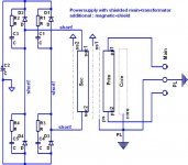
Since then I know what I had to do when I order a maintrans for sensitive setups. In my drawing one can see how a really good maintrans should built of.
Of course such high outlay is not always needful!
A link for a special kind of a (additional) magnetic screen:
www.riedel-trafobau.de
look to "single phase... page 14
Regards
Heinz!
speciall thanks to Eva for his nice work!
Now we know that this thing has nothing to do with revers-current of the diode. Also it is clear how we can damp oscillations.
Thank You Christer for nice work from Mr. Hagermann...many formulas for a simple thing and of course he`s right.
I was pushed by praxis to this problem some years earlier.
I had to design a 400VA current-amp which had to deliver beside 120A RMS also 60mA (in 5 ranges).When the amp put out 60mA I find on the signal riding mainfrequency-spikes. The reason for this we know now and also what to do.
This was some work because the amp was powered by 3 phases and used therefore 12 diodes ,I used the same as Eva mentions!
But this helps not enough : now the spikes on outputsignal get smaller but was`d still visible even I tried a lot!
My chief in this time found at least a (expensive) solution which does its job perfekt : we changed the big maintrans to a shielded one.
Even when I for test cut out my snubber the output stays clean!
Why arent the snubber not successful (enough)?
Well remember the "exciting-signal" is despite damping still present!
But with complete screening it don`t get far!
I must admit that the amp has a floating powersupply which is threrefore very delicate.
(I used a "normal" voltage-poweramplfier but the output was grounded over a resistor and the "ex"-ground of the powersupply is now a current-output)
Since then I know what I had to do when I order a maintrans for sensitive setups. In my drawing one can see how a really good maintrans should built of.
Of course such high outlay is not always needful!
A link for a special kind of a (additional) magnetic screen:
www.riedel-trafobau.de
look to "single phase... page 14
Regards
Heinz!
Attachments
Looks good, go on!
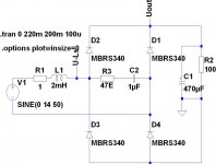
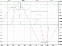
I take now a bridge and try to reduce the aruptness of the "exciting-signal" without too much losses.
It seems to work so that no shielding should be necessary.
Ls is the same 2mH and swing together with 1uF from snubber.
Fres is about 3.6 kHz = 80us falltime.
Resulting Z is about 45E. Damping therefore
with R-snubber = 47E.
Here is the circuit.
Attachments
Evas measurements are not really surprising; they are rather consistent with what some others, including myself, has measured. However, the point of all this is that there are people who claim there are effects which are difficult to measure. In audio we often have the situation where people claim they can hear a difference when none can be measured. But in this case we have people who claim not only that a difference can be heard, but also that it can be measured, but that it is very hard or impossible to measure it without special equipment like RF spectrum analyzers. I am not so sure that that makes sense, but that is what we are trying to figure out, or so I thought. I think a lot of these diode discussions go back to this posting by John Curl on AudioAsylum
http://db.audioasylum.com/cgi/m.mpl...&highlight=rf+equipment+john+curl&r=&session=
although I realize now then I reread it that he doesn't actually claim an RF spectrum analyzer is necessary to measure something.
http://db.audioasylum.com/cgi/m.mpl...&highlight=rf+equipment+john+curl&r=&session=
although I realize now then I reread it that he doesn't actually claim an RF spectrum analyzer is necessary to measure something.
powerbecker:
The software package that comes with my oscilloscope produces huge pictures, and I can't reduce them because when I do so the lines disappear and everything gets distorted. Try to configure your video adapter to 1024x768 temporally so that you can see them more comfortably.
Christer:
The funniest part is that I have clearly measured it with just a 100Ms/s oscilloscope, but I can't hear any change at all 😀 I'm happy just because it radiates less stuff to the ambient. I think that mystifying things is not a healty practice, at least in electronics. Once myths are created, it takes a lot of effort to dismantle them.
PD: I forgot to mention that ultrafast and schottky diodes ring almost in the same way in SMPS.
Eva said:I think that mystifying things is not a healty practice, at least in electronics. Once myths are created, it takes a lot of effort to dismantle them.
I agree, but at the same time one should also keep an open mind and be aware that most theory used in practice and taught to engineers is simplified and only valid under certain assumptions. Usually those assumptions hold, which is why the simplified theory works so well, but one must not fall into the trap of believing that the assumptions always hold. As for measurements, there are usually a number of standard procedures for how to measure, but occasionally those may not be sufficient, and one has to figure out alternative ways to capture a phenomenon. All too often we hear experienced EEs claim things based on the straight-forward textbook theories and their own experience, while at the same time there is more refined theory contradicting what they say, or there are examples of engineers who actually do have a different and more refined experience and have measured effects the first engineer claimed not to exist. Of course, one most not fall into the opposite trap either, and belive that there is some unanticipated phenomenon just because some people think there is one, or claim to hear one. I am the first to admit the existence of subjective bias in our hearing. I just don't want to jump to conlusions too quickly either way.
This is not in anyway meant as any critisism towards you (or anybody else in particular). I understand you are a knowledgable and experienced EE and I usually value your comments highly.
I agree 🙂 but there is an ever funnier fact about that story: I'm not an EE (feel free to laugh if you wish), I just enjoy experimentation and measurement.
Eva said:I agree 🙂 but there is an ever funnier fact about that story: I'm not an EE (feel free to laugh if you wish), I just enjoy experimentation and measurement.
You fooled me at least, and I have a strong feeling you areoften more reliable than many EEs. 🙂

- Home
- Amplifiers
- Power Supplies
- Fast Recovery rectifier diodes