jackinnj said:you can observe the phenomena Jan describes with a decent 'scope using the AC input -- there can be many microvolts of RF ripple which, because of their comparatively short wave-length -- propogate themselves all over the place. it's not just the diode, it's the transformer leakage inductance, interwinding capacitance, etc.
with one very inexpensive, beastly torroid bought off EBay I experienced zero, zip, nada, niente RF ripple on the DC power rails using MUR860's. with another high quality EI transformer from a cannibalized HP meter you could detect the ripple with an RFI sniffer on the HP 3585a spectrum analyzer. it pays to measure.
by the way, Analog Devices has reprinted their amusing tale of ADC problems in the teeth of RFI.
Hi to all
In my opinion jackinnj tell us the most interesting!

So far as I know it`s in the case of a main-rectifier not important how quick the diode switches.
BUT: every diode has a capacity (schottky has a bigger on!) as also a smaller over the secondary windings.
These capacitys get in resonance with the also always present leakage-inductance as soon the current through the diode goes to zero.
As both are small the frequency is high.
Toroids have in contrast to EI`s smaller leakage-inductances so in the resonance-circuit is stored less energy and so the hf soon "disappears".
If you put some damping-R in the resonance-circuit (in form of a snubber over the diode) the hf disappears even quicker.
Without leakage inductances there will be no hf-noise!
Jan
You done already some simulations may be You are so kind to do some more.
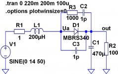
For example You can switch 2mH as leakage-inductance before the diode and over the "ideal-diode-model" some 100pF.
You should use small timesteps so it takes a time!
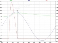
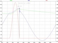
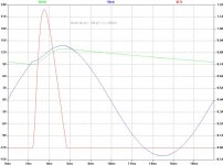
Please observe what happend at the node
leakage-inductances/diode.
You can also try a "real model diode".
What happend with a snubber?
Regards
Heinz!
Heinz,
I have earlier done some simulations more or less of the kind you ask for. I haven't saved any data, though, so I can only recapitulate from memory. Originally I was just curious to see if the phenomenon could be produced in a Spice simulation at all. It turned out to be no problem to show turn-off oscillations for diodes. However, not surprisingly there must be inductance in the circuit. I also compared a few of the diode models that come with LTSpice, and while the ordinary (don't know if they were fast recovery, though) diodes could quite a lot of oscillation, the Schottky diode didn't show any oscillation (or so little that it was negligible in comparison with the others. I also did some snubber experiments, but I never tried to calculate optimum values á la Hagermann, so I just experimented a bit to see that the snubbers affected the oscillations.
I think you are missing the point about Schottky diodes. It is true that the diode capacitance takes part in the LC tank that causes oscillation. However, there must be an excitation signal to get an oscillation. With ordinary diodes, it is the reverese current at turn off that excites the LC tank. With Schottkys, there is no reverse current, so there is practically no excitation signal. At least that is how I have understood it.
snip/Crister
However, there must be an excitation signal to get an oscillation. With ordinary diodes, it is the reverese current at turn off that excites the LC tank. With Schottkys, there is no reverse current, so there is practically no excitation signal. At least that is how I have understood it.
Hi Crister,
thank You for reply.
The "excitation signal" is coming from a sudden revers-VOLTAGE
over the diode when in case of a big leakage-inductance (Ls) the diode-current goes zero.
This voltage-jump charges the capacity in the diode. This charged capacitor then starts to "play" with Ls : hf is there!
But from what came this revers-voltage jump?
If a Ls is present the current through the diode lags after the mainvoltage. When current goes to zero the voltage on the anode goes down to the mainvoltage.
Do of this current-lagging the mainvoltage is now already much smaller so the anode steps down:
this is the excitation signal!
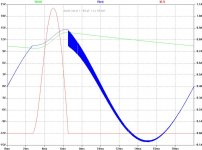
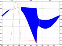
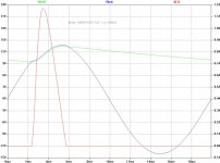
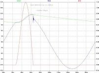
For better clarity I have done some simulations.
I use only the ideal-diode or a On-Schottky from LtSpice.
I think You will agree that in both no revers-current will appear .
Because big attachments are forbidden I must sent some posts.
Here you can see the circuit.
However, there must be an excitation signal to get an oscillation. With ordinary diodes, it is the reverese current at turn off that excites the LC tank. With Schottkys, there is no reverse current, so there is practically no excitation signal. At least that is how I have understood it.
Hi Crister,
thank You for reply.
The "excitation signal" is coming from a sudden revers-VOLTAGE
over the diode when in case of a big leakage-inductance (Ls) the diode-current goes zero.
This voltage-jump charges the capacity in the diode. This charged capacitor then starts to "play" with Ls : hf is there!
But from what came this revers-voltage jump?
If a Ls is present the current through the diode lags after the mainvoltage. When current goes to zero the voltage on the anode goes down to the mainvoltage.
Do of this current-lagging the mainvoltage is now already much smaller so the anode steps down:
this is the excitation signal!
For better clarity I have done some simulations.
I use only the ideal-diode or a On-Schottky from LtSpice.
I think You will agree that in both no revers-current will appear .
Because big attachments are forbidden I must sent some posts.
Here you can see the circuit.
Attachments
These things can hardly be propery simulated because it's very hard to model transformer distributed capacitance and inductance and diode reverse recovery phenomena.
In practice, leakage inductances are somewhat smaller than 2mH, particularly when reflected into the low voltage secondary side, and diode current falling slopes are usually too small to cause enough reverse current to require a faster diode. Remember that reverse recovery behaviour is entirely dependent on the magnitude of the current falling slope.
Don't trust simulations, build some test circuits and chech with oscilloscope instead. Real circuits are just not going to work like simulatons.
My main puzzlement is to find a source of any Schottky diodes that have anywhere near enough voltage rating for 240vac (350vdc) rectification....
.... has anyone got a source for these?
.... has anyone got a source for these?
Cree or Infineon SiC shotkkies, 600v and 1200v rated parts availlable.Globulator said:My main puzzlement is to find a source of any Schottky diodes that have anywhere near enough voltage rating for 240vac (350vdc) rectification....
.... has anyone got a source for these?
Eva,
I agree one should be careful interpreting the simulation results. When I did simulations on this I was mainly interested in the qualitative behaviour, that is, whether such a phenomenon could be provoked at all in a simulation, since it was claimed to exist in reality.
The problem with measuring this is that it seems difficult to measure. I tried using straightforward methods and a plain scope only in this thread
www.diyaudio.com/forums/showthread.php?s=&threadid=8683&perpage=10&highlight=&pagenumber=1
but couldn't detect any ringing. John Curl remarked then, and has said so also on earlier occasions, that the problem is there, but cannot be measured without special equipment. I think he used RF equipment in his first experiments.
Heinz,
I have no immediate comment to your sims, but I don't think they agree quite with what I got. I don't have any Spice up and running for the moment, so I cannot check what I get with your component values, but your results surprise me.
Christer said:
I have no immediate comment to your sims, but I don't think they agree quite with what I got. I don't have any Spice up and running for the moment, so I cannot check what I get with your component values, but your results surprise me.
I replicated heinz sims with similar results. As they seemed real strange I built and measured some real-world circuits:
1000uF 40v filtering cap with 100R load, MBR340, SF4007TFK, MBR160, MR854 diodes at choice.
tranny n. 1:
15VAC appr. 20VA toroid, secondary leakage inductance 0.16mH
Not any sort of oscillation visible on normal 100MHZ scope.
tranny n. 2: black horse of the test 😀 double insulated 2x18VAC 14VA pcb-mount potted E-core?? transformer with Whopping 20mH of leakage inductance. Had to measure twice on lcr bridge to believe.
~100khz oscillation visible at diode turn-off, max amplitude around 10 volts! for 2 cycles. attenuates quicly after couple of cycles.
(even measured third tranny, small 10VA 12VAC AC-AC adapter, 1.7mH leakage)
In all tests all diodes showed similar waveforms exept MBR160 wich burned short-circuit. 😀 Maybe killed it with inductive kickback.
Its also good to notice freq and current of these oscillation in spice. 330khz with 1mA peak inductor current doesnt sound so bad anymore, not much of danger from inductive coupling at these current levels.
All very interesting posts guys! What I noticed is the influence of the transformer leakage inductance. In other threads I advocated the use of transformers (for low power apps anyway) with loose coupling between the prim and sec, - definitely no toroids, to keep the mains borne noise and junk out of the secondary. Now it seems that such a transformer would be prone to causing the kind of diode switch-off bursts we have seen. Is this a valid assumption?
Jan Didden
Jan Didden
powerbecker said:.....
The "excitation signal" is coming from a sudden revers-VOLTAGE
over the diode when in case of a big leakage-inductance (Ls) the diode-current goes zero.
This voltage-jump charges the capacity in the diode. This charged capacitor then starts to "play" with Ls : hf is there!
.......
Hi,
Thanks for your effords.
It's possible to replace the load resistor with two current sinks:
one high current DC (or low frequency modulated) and second small current high frequency modulated (10kHz or so) in your simulations?
Regards,
Milan
Very interesting tests, especially as I'm finalising the design of a PSU (Maplin 240V@100mA + 6.3V@1.5A) for a phono preamp.
I'm planning on rectifying to c.350v into a 500v 50mF-100ohm-50mF filter, then using a BU508 (common collector) based NPN series regulate to c.300V (using a current source based V ref) and then down to 250V with a shunt ECC88 (just because it matches the other 3 tubes!) .
I'm hoping this will give good rejection etc so I now have two questions:
1) How do I measure the inductance of the secondary (I have an L meter (a fancy multimeter)) - do I short the primary? What is max/min mains impedance? Could this be why some mains cables alledgedly sound different?
2) Using a standard bridge (KBPC606) how do I calculate the value of the snubber caps. I'm also assuming snubber caps must be placed over each diode - or will one do across somewhere else?
Thanks!
mzzj said:
tranny n. 2: black horse of the test 😀 double insulated 2x18VAC 14VA pcb-mount potted E-core?? transformer with Whopping 20mH of leakage inductance. Had to measure twice on lcr bridge to believe.
~100khz oscillation visible at diode turn-off, max amplitude around 10 volts! for 2 cycles. attenuates quicly after couple of cycles.
I guess that this tranny is short-circuit proof, would explain extremely high leakage inductance.
- Home
- Amplifiers
- Power Supplies
- Fast Recovery rectifier diodes