454Casull said:
does that midrange have this coil technology?
@ Noob: yes, it does. There was a review in HobbyHifi, and they showed the effect of shorting this winding or connecting it to the amp (in parallel, as I recall) on inmpedance and FR. Harmonic distortion was also excellent, but they didn't say which connection they used for this. FR and CSD or this driver were typical for PA, i.e. poor.
@ Bill:
Go to www.e44.com, search for HM170Z2 and when the search result comes up, click on the blue "i" for information. You will get a screen which contains a javascript button that will display the pdf data sheet.
Do you have any comments on outside vs. inside full length sleeve? Any disadvantages other than slightly higher resistance?
Do you have any handwaiving argument as to why the effectiveness of a Faraday sleeve diminishes towards lower frequencies while the comp coils' does not? Even at LF, the current in the sleeve will mirror the current in the VC if coupling ratio and sleeve resistance permit. Coupling ratio is a question of geometry, so it does not change. However, inductance of both VC and sleeve fall, leaving the resistance as the limiting factor at LF. Am I on the right track?
Greetings,
Eric
capslock said:Do you have any handwaiving argument as to why the effectiveness of a Faraday sleeve diminishes towards lower frequencies while the comp coils' does not? Even at LF, the current in the sleeve will mirror the current in the VC if coupling ratio and sleeve resistance permit. Coupling ratio is a question of geometry, so it does not change. However, inductance of both VC and sleeve fall, leaving the resistance as the limiting factor at LF.
Yes, it looks like it. Take a look at here formula 21a at page 21
http://www.geocities.com/pirimoglu/Articles/FaradayRingsVoiceCoilImpedance.pdf
That formula assumes there is perfect coupling between voice coil and shorting ring.
If I rearrange the terms in that 21a, the imaginary part of the voice coil impedance becomes:
Img(Z) = w Lvc [1 - (1 / (((Rsr / (w Lsr ))^2) + 1) ]
Lvc is voice coil inductance, Rsr is shorting ring's resistance, Lsr is shorting rings inductance, w is angular frequency, i.e 2xpixf.
In order for a good reduction of voice coil inductance, the expression after "1 - " needs to be as close to 1 as possible. As w goes to zero, that expression goes to zero as well, if Rsr is not zero. If Rsr is very small, that expression will go to zero slowly as w goes to zero than a case where Rsr is high. If Rsr is absolutely zero, that expression will be "1" regardless of the value of w, which will remove the imaginary component of voice coil impedance making it pure resistive, regardless of frequency. BTW the current in the shorting ring is not exactly a mirror of the voice coil's current. They are related by the number of turnings of the voice coil, since shorting ring is just one turn.
In case of using an active secondary coil, the current in the secondary coil is actively generated and is made to actively mirror the current in the voice coil. So this will be independent of the frequency. If you think the limit case of DC, where w = 0, no current will be induced in the shorting ring, so it has no effect there. An active secondary coil will still have its effect with DC. It will prevent the modulation of the air gap flux by voice coil current even under DC input. Birt's JAES paper was based on preventing the modulation of the air gap flux, not trying to control the inductance of the voice coil. I wouldn't dismiss the benefits of a very thick shorting ring at the base of the pole piece or at the innerside of the magnet. There is room in those places to be able to put very thick low resistance shorting rings. My guesstimate is they will be effective to control the modulation of the air gap flux, even under low frequencies. They won't have much effect of reducing voice coil inductance or reducing the modulation of it, but they do their job for low frequencies, where the reactance of the voice coil inductance is low also wrt to the resistance of the voice coil. Depending on how large the voice coil inductance is, at low frequencies it won't have much effect on the resultant movement of the cone, because its reactance will be low; voice coil resistance will have a more say in the voice coil current. I think this is also why you can see a thick ring on the base, and a sleeve on the pole piece at many new designs. The former is for reducing the air gap fluxmodulation, the latter is for reducing the modulation of the voice coil inductance.
I also think an active coil just besides the voice coil has the disadvantage of increasing the ambient temperature around the voice coil. The active coil having a DCR, will give out heat as current flows in it. A shorting ring does just the opposite, being a good heat conductor such as copper, it helps with cooling the voice coil. The induced currents on the shorting ring copper will also cause some heat, but it will be very small, assuming shorting ring has a low enough internal resistance. Thinking about it, my guess is a sleeve and cap would work better than an active stationary secondary coil to reduce inductance modulation, especially to reduce inductance modulation by displacement. Sleeve and cap can be positioned in an optimized way to reduce the inductance modulation by displacement, but I don't know if you can do it with active coil without any feedback of the voice coil position. As Birt was using it, I think such an active coil is more beneficial to control air gap flux modulation, which was done by putting it at the base of the pole piece.
Add to all this the changing internal resistance of the shorting ring with frequency because of skin effect, it gets a whole lot more complicated. I plan to look at this side of it in more detail, Vanderkooy at a paper of his looks at it with induced currents on pole pieces but I think it is criticized that his results doesn't really follow in practice with real world driver impedances.
Something like that anyways.... Just my 2 cents
P.S. IIRC, I had seen SS 12M's inductance vs displacement curve in Voice Coil magazine, it wasn't flat with zero slope. It was a straight line with a slope, meaning voice coil inductance was varying with displacement. I also think, making the parts of the pole piece saturated is one thing, making the whole pole piece saturated is another. This is another thing I want to look into more detail if I get a chance, but again my guess is just saturating some parts of the pole piece and leaving others is not that good enough to remove the voice coil modulation. Voice coil uses almost all the volume of the pole piece by its own field inside it.
Thanks, Feyz. I've appreciated your contibutions to the Faraday-ring discussion. Your paper should be required reading for anyone interested in loudspeaker motor design. 😎
Just now, cruising this thread, another possible benefit of Faraday rings occurred to me.
I was thinking about barkhausen noise--something that typically finds its way into these discussions--and it occurred to me that a Faraday sleeve would effectively place a lowpass filter on Barkhausen noise, the tiny, sharp jumps in field strength as iron domains flip and cascade. Not a bad thing, whether or not you believe that Barkhausen noise is audible.
Thoughts?
Feyz said:
[...]
My guesstimate is they will be effective to control the modulation of the air gap flux, even under low frequencies. They won't have much effect of reducing voice coil inductance or reducing the modulation of it, but they do their job for low frequencies, where the reactance of the voice coil inductance is low also wrt to the resistance of the voice coil.
[...]
Sleeve and cap can be positioned in an optimized way to reduce the inductance modulation by displacement, but I don't know if you can do it with active coil without any feedback of the voice coil position. As Birt was using it, I think such an active coil is more beneficial to control air gap flux modulation, which was done by putting it at the base of the pole piece.
Thanks, Feyz, that was very insightful.
On the first quoted part:
I assume this is why Audax make a region of the bottom platte thinner than the surrounding material. I have not simulated it yet, but assume this ring around the pole piece is well saturated, keeping the modulation from spreading. Advantage: shorting ring saved, downside: loss of flux.
On the second quote:
Aren't sleeve and cap essentially the same thing? I assume you meant sleeve for the massive outside ring (à la Peerless)?
The only drivers I am aware of that use this approach of outside lower ring and cap are the Peerless HDS phase plug versions, which have the massive ring hidden inside the magnet, a conductive phase plug on the top of the pole piece and a 0.25 mm cap on the pole piece. which, as reported by David T, does seem to stretch into the gap, but not all the way to the lower end of the gap (no no idea why).
If the lower ring is too thick, one may end up with an inverted inductance vs. displacement curve. Dan Wiggins hinted at something in the discussion of the Extremis design, but I don't think the Extremis uses a lower ring (Adire just talks about the sleeve, and also, with Nd magnets, flux modulation is not that much of an issue as it is with ferrites.
By the way, I have a bunch of little comments on your paper. If you want to send me a Word version or an ASCII or RTF export, I can type them into the original text.
Greetings,
Eric
Bill, yes, by reducing the AC field that enters the iron and hence magnet, Faraday shielding will also reduce Barkhausen noise.
Anybody have any thoughts as to whether an outside full length sleeve has any significant downsides compared to an inside sleeve?
Anybody have any thoughts as to whether an outside full length sleeve has any significant downsides compared to an inside sleeve?
Eric,
I don 't see any downsides except for the fact that (1) there is usually less nearby iron outside the VC and (2) the VC field is slightly less dense on the outer gap face than on the inner, if you're thinking of treatment within the gap. Also, it may be a bit easier for a manufacturer to place a ring over the pole than within the top-plate gap face.
Regarding Faraday rings and Barkhausen, I was actually thinking of the potential for Barkhausen phenomena resulting from domain flips caused by lower-frequency VC signals, which a Faraday ring may not be able to prevent. However, since the domain-flip cascades introduce steps into the B field, which, I believe, result in higher-frequency harmonic content, I'm suggesting that, while even a good Faraday sleeve might not be able to prevent domain flips at LF, it might effectively filter the resulting higher-frequency noise.
I have started a new thread on dimensioning comp coils
http://www.diyaudio.com/forums/showthread.php?s=&threadid=63810
First thing to look at is a comp coil for keeping flux modulation down. Next things would be comp coils as a replacement for Faraday shields.
http://www.diyaudio.com/forums/showthread.php?s=&threadid=63810
First thing to look at is a comp coil for keeping flux modulation down. Next things would be comp coils as a replacement for Faraday shields.
Bill F. said:Eric,
I don 't see any downsides except for the fact that (1) there is usually less nearby iron outside the VC and (2) the VC field is slightly less dense on the outer gap face than on the inner, if you're thinking of treatment within the gap. Also, it may be a bit easier for a manufacturer to place a ring over the pole than within the top-plate gap face.
Bill,
I am not sure that those two points are relevant. Thinking about a shorting ring or sleeve in terms of shielding is actually misleading (I fell into that trap before).
Feyz' paper thinks about VC and shorting ring in terms of a transformer, which is a real eye opener. For good coupling, both coils should loop around the same flux, which they do with both inside and outside sleeve. Once you have good coupling, the induced current will generate a flux the change of which cancels the change of flux from the inducing coil. The induced AC field will cancel the AC field of the VC, no matter whether the sleeve is inside or outside the VC. Hence there is no AC field acting on the pole piece either way. Or am I hugely mistaken here?
The reason why I would like to use an outside sleeve is easier retrofitting. An inside sleeve would require grinding down the pole piece in all cases where a non undercut pole piece is used. An outside ring just requires unwinding two layers of a four layer VC, or no other action at all in the case of the HM170Z2, which have generous outside clearance.
Regards,
Eric
capslock said:On the second quote:
Aren't sleeve and cap essentially the same thing? I assume you meant sleeve for the massive outside ring (à la Peerless)?
I should have been more clear. By "cap" in that context I meant an additional ring like object that is placed on top of the pole piece. This extra "cap" can balance the "inverted" inductance vs displacement effect. IIRC Peerless XLS drivers have an aluminum disc like that on top of the pole piece. Also look at page 5 of B&W's white paper on 700 series, they give nice illustrations on this:
http://www.bwspeakers.com/downloadFile/technicalFeature/700SeriesWhitepaper.pdf
The only drivers I am aware of that use this approach of outside lower ring and cap are the Peerless HDS phase plug versions
JBL uses it, look at the picture
http://www.audioheritage.org/images/projectmay/technology/1500AL_draw.gif
which is taken from
http://www.audioheritage.org/html/projectmay/technology/1500al.htm
Tough this one uses a stack of copper and steel rings on the gap.
Also IIRC I had read at Revels site that the tweeter they were using at their top line had a ring at the base and a sleeve at the gap. I can't find it now at Revel's website. They had a diagram of the tweeter, which looked alot like Scan Speaks. It may be a custom build for them by Scan Speak.
I think the upper ring of a sandwiched T-shaped pole like Seas's Excel motors does the same thing. I have a hunch PE's new subwoofers which are described to have three short circuit rings uses two rings on a T-shaped pole piece and another ring at the base or inside the magnet, but that's just speculation on my part.
From the pictures on Skanning they extend and then round the sleeve on the top of the pole piece. Usher's phase plugged woofers also have a sleeve which is extend and then rounded and folded on back to the top of the pole piece. I think these are made that way to prevent that "inverted" inductance vs displacement effect. They could have just folded the copper sleeve directly on top of the pole piece.
By the way, I have a bunch of little comments on your paper. If you want to send me a Word version or an ASCII or RTF export, I can type them into the original text.
I would appreciate that, I send you an email via diyaudio, since I lost your email. If you could reply it, I will send the doc to you.
I am not sure that those two points are relevant. Thinking about a shorting ring or sleeve in terms of shielding is actually misleading (I fell into that trap before).
Feyz' paper thinks about VC and shorting ring in terms of a transformer, which is a real eye opener. For good coupling, both coils should loop around the same flux, which they do with both inside and outside sleeve. Once you have good coupling, the induced current will generate a flux the change of which cancels the change of flux from the inducing coil. The induced AC field will cancel the AC field of the VC, no matter whether the sleeve is inside or outside the VC. Hence there is no AC field acting on the pole piece either way. Or am I hugely mistaken here?
Eric,
I agree. However, I think this may be a question of different assumptions. If you're assuming that a Faraday ring, whether within or without the VC, couples perfectly with the entire VC field, then you'll have perfect cancellation everywhere. But I believe what really happens is far from perfect coupling.
The Faraday ring can only couple with the portion of the alternating field that enters it. You can see in the sims I posted earlier that, when only an inner Faraday ring is used, only the inward portion of the VC field couples with it.
So, if you place a Faraday ring outside the VC, I believe you'll reap the benefit of less of the field reaching into the top plate, but the field will still penetrate the pole. That's the kernal of my point. (I hope I understood you correctly and addressed your point. 🙂 )
Yes, you addressed my point 🙂
I still am not sure I get the point of where you think my assumptions clash with reality.
Let's assume we just have the VC and the outside sleeve and no iron system. All the flux lines of the VC go through its inside and hence also through the inside of the outside sleeve. All flux lines outside the diameter of the VC essentially go in the opposite direction. However, they are widely spaced and hence only precious few will go through the gap between outside sleeve and VC. Hence the coupling is nearly ideal.
The pole piece (if it is there) carries a DC field which does not bother the VC & sleeve. The AC field of the VC is essentially compensated for, so we have minimal interaction of the VC with the pole piece, or for that matter, the rest of the iron system.
What am I missing?
I seem to be too thick tonight to understand that sentence at all. Could you elaborate?
Thanks,
Eric
I still am not sure I get the point of where you think my assumptions clash with reality.
Let's assume we just have the VC and the outside sleeve and no iron system. All the flux lines of the VC go through its inside and hence also through the inside of the outside sleeve. All flux lines outside the diameter of the VC essentially go in the opposite direction. However, they are widely spaced and hence only precious few will go through the gap between outside sleeve and VC. Hence the coupling is nearly ideal.
The pole piece (if it is there) carries a DC field which does not bother the VC & sleeve. The AC field of the VC is essentially compensated for, so we have minimal interaction of the VC with the pole piece, or for that matter, the rest of the iron system.
What am I missing?
Bill F. said:
So, if you place a Faraday ring outside the VC, I believe you'll reap the benefit of less of the field reaching into the top plate, but the field will still penetrate the pole.
I seem to be too thick tonight to understand that sentence at all. Could you elaborate?
Thanks,
Eric
There's a good chance I'm the thick one and totally misunderstanding what you're saying, but I think I'm hearing you say that, essentially, a single Faraday sleeve outside the VC should significantly reduce flux modulation in the pole. That's the point I'm arguing against. 🙂
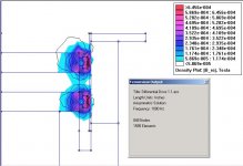
I hope a picture is worth 1k words.
Same DD motor @ 1kHz with a single Faraday sleeve outside the VC. Notice that the VC field lines do penetrate into the pole in this case, whereas they didn't in the inner Faraday sleeve scenario.
I hope a picture is worth 1k words.
Same DD motor @ 1kHz with a single Faraday sleeve outside the VC. Notice that the VC field lines do penetrate into the pole in this case, whereas they didn't in the inner Faraday sleeve scenario.
Attachments
capslock said:
What am I missing?
I think what you are missing is, for perfect coupling the faraday ring and the voice coil should have exactly the same diameter, which can't be unless they are intertwined🙂. Whether the faraday ring sleeve is inside or outside of the coil, coil and faraday ring may see the same flux change, and the flux change will cause an induced current on the sleeve. But this induced current on the ring generates a field on the overall cross section area of its, which is different then the cross section area of the voice coil. I haven't set done and did any calculations, but I think the larger the difference between the cross section areas of the ring and the coil the less coupling they will have. Math can prove me wrong though 🙂
I think what Bill is demonstrating is, when the ring is inside and close to the pole piece, it cancels the flux change inside the pole piece, but not on the top and bottom plates that effectively. When the ring is outside the coil and close to top and bottom plates it cancels the flux change inside the top and bottom plates but not that effectively the change on the pole piece. Since pole piece has more iron than top and bottom pieces, it might be the first choice to place the ring close to it. In Bill's simulations, a ring outside the coil is still beneficial if you compare it to the case with no ring.
BTW, I am confused to which one is which 🙂 I think in the below one the ring is close to the pole piece and inside the coils:
http://www.diyaudio.com/forums/attachment.php?s=&postid=717939&stamp=1126030738
And on this one I think the middle version is the one that has faraday ring on the outside of the coil. Or I got the geometry or wrong 🙂
http://www.diyaudio.com/forums/attachment.php?s=&postid=706194&stamp=1124390327
Sorry, it's not very clear in my FEMM screenshots, but the left border of each sim is the motor centerline, (axisymetric problem) so you're moving outward as you move right. 🙂
Hi,
I have a question not directly anything to do with Faradays ring, but as it covers the modulation of the magnetic field when the VC moves in the airgap I would ask about if anybdoy knows anything about pole pieces (used in a loudspeaker motor) molded under a magnetic field giving the grains an orientaion so they should be oriented in the magnetic field path in a given conventional loudspeaker motor design.
Would anybody make a comment or have anything to contribute in the matter, does any loudspeaker element manufacturer use it?
Regards, Michael©
Michael, unfortunately, I've never heard about that kind of thing. It probably does not make a lot of sense, because soft iron, by definition, does not hold on to a magnetization all too well.
Bill, Feyz: thanks for your explanations. It still does not make intuitive sense to me, but I guess I will have to figure out how to simulate an AC field in Maxwell SV (or tackle the FEMM manual, which repelled me even more than the Maxwell manual on first sight). Assuming the simulator doesn't lie, I can maybe find out what the imperfection is that gives rise to the assymetric screening.
Feyz, I received your doc, am just currently snowed under with work. Will undig the printout and transfer my remarks some time soon.
What a fantastic discussion! I don't know why it just stopped.
It would seem that a long copper sleeve inside and outside the voice coil would be the best place to start.
What could I do to the 830452?
Drawing is roughly to scale. I suppose the aluminium cap and sleeve does work but the voice coil has many turns.
Would a copper sleeve inside/outside the voice coil make a significant difference to the inductance?
Does the conductive former have anything to do with voice coil inductance and/or flux modulation and/or the effect of a Faraday ring?
Perhaps I should wind a new thinner voice coil on a slightly larger nonconductive former. This would make space for copper sleeves inside and outside.
An externally hosted image should be here but it was not working when we last tested it.
- Status
- Not open for further replies.
- Home
- Loudspeakers
- Multi-Way
- Faraday rings