I modeled the driver I have with several different coil geometries. I found one that will completely eliminate any inductance, but it would almost triple the series resistance over what the voice alone is.
The Hyperdynamics-patented topology JBL licenses (they call it Differential Drive) seems to me a more efficient way of cancelling inductance.
Thoughts?
Attachments

that look an essentially underhung design so surely its going to be HUGE when you develop a high XMax design (I'm looking at a sub here).
Nice you brought it up though.
Nice you brought it up though.
Yes, that's my simplified drawing of an underhung application of Differential Drive, but JBL more commonly uses a long-excursion variation--picture the same thing, just overhung.
Differential Drive PDF
Differential Drive PDF
Bill F. said:
The Hyperdynamics-patented topology JBL licenses (they call it Differential Drive) seems to me a more efficient way of cancelling inductance.
Thoughts?
Well, we were talking about modifying an existing magnet structure, so it's not really possible to do that for this case... However, I just ran a quick model (I couldn't find my results from the last time I did it), and there still is inductance - it is not totally eliminated. The inductance is perfectly symmetrical, though (but not necessarily flat, although it was pretty flat in my case). This is just for a theoretical case, though. If you added an aluminum frame that was not symmetric, you would loose your nice Le vs x curve.
Interesting, John.
I hadn't gotten around to modeling DD, but just looking at it, I'd thought the inductance of the counter-wound VCs would cancel--but I guess not.
Would you be willing to email your FEMM file to billfagal at gmail dot com? I'm intrigued.
(Sorry for all this being OT.)
Bill
I hadn't gotten around to modeling DD, but just looking at it, I'd thought the inductance of the counter-wound VCs would cancel--but I guess not.
Would you be willing to email your FEMM file to billfagal at gmail dot com? I'm intrigued.
(Sorry for all this being OT.)
Bill
How does this compare to Manger's two voice coils?
If I remember correctly Manger's website mention something like a mechanically connected in series but electrically connected in reverse voice coils that reduce the inductance to allow for fast rise time, and again if I remember correctly they were saying that this was a very old patent of theirs. Is anybody familiar what does Manger do with the voice coils? At one time I had tried to search the US patent db for the Manger patent, but I think it belonged to an old era where US patent DB doesn't allow searching with keywords, so I couldn't find it.
From the short description I had read on Manger drive, this sounded the same thing as the JBL patent, if this is true, it should make JBL patent, well not so much of a real patent I guess, because it would be a prior art. Does anybody know the details of how Manger manages to have a low inductance with two voice coils?
Bill F. said:I hadn't gotten around to modeling DD, but just looking at it, I'd thought the inductance of the counter-wound VCs would cancel--but I guess not.
I don't claim to be a magnetics expert. In fact it confuses the hell out of me. However, I believe this is a matter of mutual inductance. A high mutual inductance means that a current in one coil will induce a proportional current in the other coil (proportional to the turns ratio that is). The coils in the JBL motor are pretty far apart and if you're saturating the pole piece, there is a lot of flux that is not following the steel circuit...hence the mutual inductance is not that high. Putting the coils physically closer will get you a higher mutual inductance. Compare the JBL motor to a transformer, for instance. The coils are (usually) interleaved and the iron isn't saturated, so you'll get a much higher mutual inductance in the transformer.
John
Re: How does this compare to Manger's two voice coils?
Nevermind what I wrote before. I just relooked at Manger's website. They are using two voice coils in a single air gap. This is very different than what JBL is doing.
Feyz said:.....
From the short description I had read on Manger drive, this sounded the same thing as the JBL patent, if this is true, it should make JBL patent, well not so much of a real patent I guess, because it would be a prior art. Does anybody know the details of how Manger manages to have a low inductance with two voice coils?
Nevermind what I wrote before. I just relooked at Manger's website. They are using two voice coils in a single air gap. This is very different than what JBL is doing.
I believe this is a matter of mutual inductance. A high mutual inductance means that a current in one coil will induce a proportional current in the other coil (proportional to the turns ratio that is).
Hi John,
Your descriptions of 2nd-order-gradient bass alignments have influenced my current/future experiments--thanks!

I don't think the coil interaction is raising inductance in this case. Rather, since the opposite fields repel each other, I'd expect them to reduce total inductance, as illustrated in the attached two FEMM plots (air-core single turns, first with current flowing in the same direction, then opposing).
Attachments

Manger patents
Feyz,
I have the PDFs of the older Manger patents. Post your email address and I will mail them to you. I had meant to read them for a long time, maybe I will do that before sending them and give you a summary (after all, they are poors scans of the typewritten German patent apps, so machine translation will not do a lot of good).
Greetings,
Eric
Bill F. said:
Hi John,
Your descriptions of 2nd-order-gradient bass alignments have influenced my current/future experiments--thanks!
My pleasure
I don't think the coil interaction is raising inductance in this case. Rather, since the opposite fields repel each other, I'd expect them to reduce total inductance, as illustrated in the attached two FEMM plots (air-core single turns, first with current flowing in the same direction, then opposing).
Right. Sorry if I wasn't clear. The amount of cancellation depends on the mutual inductance. A high mutual inductance means a higher degree of cancellation (lower net inductance). The JBL motor has lower mutual inductance than a motor with the compensating coil close to the voice coil. Hence it will have a higher inductance.
best regards, John
Right. Sorry if I wasn't clear. The amount of cancellation depends on the mutual inductance. A high mutual inductance means a higher degree of cancellation (lower net inductance).
Ah, yes. Sorry I misunderstood you, John (H).
John (S), I'm curious about your DD model. The stray flux does appear similar to the free air coils. Did you compare the coils' inductance in free air to their inductance with the magnetic return circuit in place? I would hazard a guess the two readings might be quite close.
Bill
Hi Bill,
If you've got time to burn, how about simulating two interleaved coils. I'm just curious to see how that compares--what kind of cancellation you get.
John
If you've got time to burn, how about simulating two interleaved coils. I'm just curious to see how that compares--what kind of cancellation you get.
John

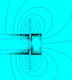
I was just playing around with a DD sim with varying levels of Faraday treatment, and I thought I'd share a nice visual illustration of how full-length faraday rings shield the ferromagnetic motor parts from alternating VC fields.
The sim is an 4" dia. underhung differential-drive motor with a NdFeB magnet in the pole. Yoke is 1006 steel, and Faraday rings are 1/20" thick copper. Counterwound single-turn copper VCs carry 10A @ 1kHz.
From left to right: No Faraday rings; ring inside VC; rings inside and outside VC.
The sim is an 4" dia. underhung differential-drive motor with a NdFeB magnet in the pole. Yoke is 1006 steel, and Faraday rings are 1/20" thick copper. Counterwound single-turn copper VCs carry 10A @ 1kHz.
From left to right: No Faraday rings; ring inside VC; rings inside and outside VC.
Attachments

Bill F. said:
John (S), I'm curious about your DD model. The stray flux does appear similar to the free air coils. Did you compare the coils' inductance in free air to their inductance with the magnetic return circuit in place? I would hazard a guess the two readings might be quite close.
Bill
I just tried that and one coil on the air core is around 3.6 vs 5.3 for the magnet assembly, so the inductance does go up with some steel in there. Those numbers aren't actually the inductances, but would be directly proportional to inductance.
If you've got time to burn, how about simulating two interleaved coils. I'm just curious to see how that compares--what kind of cancellation you get.
John,
Wouldn't interleaving coils wired with opposite polarity kill your BL? It would kind of defeat the purpose...
John
Bill F. said:I was just playing around with a DD sim with varying levels of Faraday treatment, and I thought I'd share a nice visual illustration of how full-length faraday rings shield the ferromagnetic motor parts from alternating VC fields.
The sim is an 4" dia. underhung differential-drive motor with a NdFeB magnet in the pole. Yoke is 1006 steel, and Faraday rings are 1/20" thick copper. Counterwound single-turn copper VCs carry 10A @ 1kHz.
From left to right: No Faraday rings; ring inside VC; rings inside and outside VC.
that is quite amazing....that's for illustrating that
WOW Bill F....excellent work on DD-Faraday simulation.
Your simulation opens the question on selecting a DD drive motor over a radial motor as used in Aura for an underhung design. A radial motor with Faraday rings always looked superior for modest Xmax speakers, and your simulation seems to support this. High efficiency and high detail are more important to me than Xmax.
Your simulation opens the question on selecting a DD drive motor over a radial motor as used in Aura for an underhung design. A radial motor with Faraday rings always looked superior for modest Xmax speakers, and your simulation seems to support this. High efficiency and high detail are more important to me than Xmax.
Attachments
LineSource said:WOW Bill F....excellent work on DD-Faraday simulation.
Your simulation opens the question on selecting a DD drive motor over a radial motor as used in Aura for an underhung design. A radial motor with Faraday rings always looked superior for modest Xmax speakers, and your simulation seems to support this. High efficiency and high detail are more important to me than Xmax.
yup... but.... there is one speaker with 3 faraday rings and 15 mm one way 😛
- Status
- Not open for further replies.
- Home
- Loudspeakers
- Multi-Way
- Faraday rings