Bill, was this FEMM?
With the field this nicely shielded, why would you still want to use DD? The main point of DD is to avoid modulation of iron magnetization, isn't it?
Greetings,
Eric
With the field this nicely shielded, why would you still want to use DD? The main point of DD is to avoid modulation of iron magnetization, isn't it?
Greetings,
Eric
John Sheerin said:
John,
Wouldn't interleaving coils wired with opposite polarity kill your BL? It would kind of defeat the purpose...
John
I am just wondering how the mutual inductance in these speaker simulations compare to the mutual inductance of interleaved coils in a transformer.
John
Bill F. said:The sim is an 4" dia. underhung differential-drive motor with a NdFeB magnet in the pole. Yoke is 1006 steel, and Faraday rings are 1/20" thick copper. Counterwound single-turn copper VCs carry 10A @ 1kHz.
Bill,
I'm always free with other people's time...how about trying this at 100Hz or even 10Hz. As I recall Birt was advocating compensation coils over Faraday rings for woofers because they work better at low frequencies. The DD solution, since it is basically a compensating coil, may be relatively more attractive for a woofer than is indicated in your simulation at 1kHz.
John
Bill, was this FEMM?
Correctamundo.
With the field this nicely shielded, why would you still want to use DD? The main point of DD is to avoid modulation of iron magnetization, isn't it?
Faraday rings' sheilding effectivness drops with frequency, so I still like the idea of DD or a compensating coil for their low-frequency behavior, though I'm sure some might debate their audible benefits at low frequency.
how about trying this at 100Hz or even 10Hz. As I recall Birt was advocating compensation coils over Faraday rings for woofers because they work better at low frequencies. The DD solution, since it is basically a compensating coil, may be relatively more attractive for a woofer than is indicated in your simulation at 1kHz.
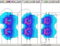
Apart from any bandwidth gained from lower Le, yes, I believe that if the counter-wound VCs offer any audible improvement, it would be midbass and down, where Faraday rings become less effective sheilds, as illustrated below. (Same motor and Faraday treatment as before, but now at 100Hz.) The Faraday rings are practically out of the picture at this freq.
Attachments
outside Faraday sleeve?
I scooped up some surplus Audax HM170Z2 on ebay. Get them while you can, nice built quality and good for modding.
The pole piece is cold forged but with a surprisingly complex geometry. It is basically a straight cylinder with no undercut, but it is extended by about 6 mm. The extended section is 1 mm smaller in diameter than the pole itself, and is has a conicial cutout on the inside. I have not yet simulated this, but I have worked on similar geometries, and a very nicely symmetrical Bxl curve can be achieved with this type of geometry. This might explain the good distortion behavior that most HM series drivers exhibit in the total absence of any Faraday shielding.
The VC is also yummy! Kapton former (does not bend as easily as aluminum) and two layers of square wire, sealed in epoxy. The inside diameter is just 0.3 mm larger than the diameter of the pole piece, so not much room (0.15 mm) for inserting a Faraday sleeve on the pole without grinding the pole piece diameter down.
However, there is plenty of clearance on the outside. I have not yet taken the moving parts out, but I estimate almost 1 mm of clearance. The probably did this to be able to use the same top plate also with four layer VCs or to lineralize the gap by using a wide gap. It still doesn't strike me as a smart design regarding suceptibility to misalignment, though.
Anyway, I could make use of the large outside clearance and insert a long outside sleeve of about 0.5 mm wall thickness.
While outside rings that extend only over part of the length of the VC (such as the Peerless shorting ring that hides on the inside of the magnet) are a dubious affair, I would assume that a long outside sleeve would achieve a very good coupling ratio, i.e. be as efficient as an inside sleeve with the only exception being its higher resistance for the same wall thickness because of its larger diameter.
Anybody worked with or simulated outside rings?
Bill F. said:
Correctamundo.
Faraday rings' sheilding effectivness drops with frequency, so I still like the idea of DD or a compensating coil for their low-frequency behavior, though I'm sure some might debate their audible benefits at low frequency.
Apart from any bandwidth gained from lower Le, yes, I believe that if the counter-wound VCs offer any audible improvement, it would be midbass and down, where Faraday rings become less effective sheilds, as illustrated below. (Same motor and Faraday treatment as before, but now at 100Hz.) The Faraday rings are practically out of the picture at this freq.
interesting....
would a counterwound VC actually have the same characteristics as faraday for higher frequencies? or is it just one of those "compromises" everyone must make
IIRC Nick from Lambda actually boasted that his Apollo's were the only speaker ever to achieve a coil that truly behaved like an air core inductor for the entire excursion range (20 mm P2P)
Do the Apollos use compensating coils?
You get a behavior like an air core inductor if you use no shielding at all but saturate the pole piece. The Scan 12M might be an example of this (not sure how saturated the pole piece is).
Using shielding or comp coils, you actually get better (i.e. obtain lower inductance) than with an air core inductor because the field inside the inductor is blocked.
capslock said:Do the Apollos use compensating coils?
You get a behavior like an air core inductor if you use no shielding at all but saturate the pole piece. The Scan 12M might be an example of this (not sure how saturated the pole piece is).
Using shielding or comp coils, you actually get better (i.e. obtain lower inductance) than with an air core inductor because the field inside the inductor is blocked.
it's a triple faraday ring Design IIRC
I didn't know what a compensating coil is until this thread... so I can't really answer the question very well
the Le on the Apollo was 0.09mh IIRC
I'm curious though if a compensating coil would work as well... from say 200-500hz, the most important Range IMO, than faradays would there
A'noob:
Similar perhaps, since both reduce Le, but I'd hesitate to say "same" since they use two completely different mechanisms. Only building and measureing (or very thorough FEA modeling) would tell.
Well, as the above sims illustrate, even a thick full-length Faraday ring steps out of the equation at low frequencies, so any claim of air-core-like behavior would have to be at frequencies largely above a bass driver's passband.
Cap:
Went looking for the spec sheet at Audax, couldn't find the model #. Are you sure it's right?
I would guess that the behavior would only stay air-core-like until the VC field pushed the B field back enough to unsaturate the gap faces--probably wouldn't take much juice...
would a counterwound VC actually have the same characteristics as faraday for higher frequencies?
Similar perhaps, since both reduce Le, but I'd hesitate to say "same" since they use two completely different mechanisms. Only building and measureing (or very thorough FEA modeling) would tell.
IIRC Nick from Lambda actually boasted that his Apollo's were the only speaker ever to achieve a coil that truly behaved like an air core inductor for the entire excursion range (20 mm P2P)
Well, as the above sims illustrate, even a thick full-length Faraday ring steps out of the equation at low frequencies, so any claim of air-core-like behavior would have to be at frequencies largely above a bass driver's passband.
Cap:
I scooped up some surplus Audax HM170Z2 on ebay. Get them while you can, nice built quality and good for modding.
Went looking for the spec sheet at Audax, couldn't find the model #. Are you sure it's right?
You get a behavior like an air core inductor if you use no shielding at all but saturate the pole piece.
I would guess that the behavior would only stay air-core-like until the VC field pushed the B field back enough to unsaturate the gap faces--probably wouldn't take much juice...
Bill F. said:
Similar perhaps, since both reduce Le, but I'd hesitate to say "same" since they use two completely different mechanisms. Only building and measureing (or very thorough FEA modeling) would tell.
Well, as the above sims illustrate, even a thick full-length Faraday ring steps out of the equation at low frequencies, so any claim of air-core-like behavior would have to be at frequencies largely above a bass driver's passband.
Went looking for the spec sheet at Audax, couldn't find the model #. Are you sure it's right?
this is rather interesting something I'm curious about now
can say both rings and a compensating coil be used in the same design?
this peaks my curiousity because perhaps in the future I may get my speakers changed out to this coil technology... but keep my rings...
can TC sounds do this modification?
Audiophilenoob said:
this is rather interesting something I'm curious about now
can say both rings and a compensating coil be used in the same design?
this peaks my curiousity because perhaps in the future I may get my speakers changed out to this coil technology... but keep my rings...
can TC sounds do this modification?
anyone?

Bill F. said:
Sure.
best of both worlds I assume with low leakage across nearly all the bandwith?
Bill F. said:Sorry, to what are you referring? 😕
simply would the faraday rings AND coil have any disadvantages??? seemingly they would have none correct as far as inductance is concerned
for low frequencies the coil would offer superior inductance "trappings" and at higher frequencies the faraday would do what's it's designed to do correct?
so across the entire very wide bandwith of the speaker it would have miniscule inductance leakage with this design?
Ah, Okay. I was confused by the term "leakage," since it applies much more to closely-coupled electromagnetic systems (transformers) than to a loudspeaker motor.
Anyway, no, beyond the individual tradeoffs of each, I don't anticipate any additional downsides to combining a counterwound coil and Faraday rings into one motor.
Anyway, no, beyond the individual tradeoffs of each, I don't anticipate any additional downsides to combining a counterwound coil and Faraday rings into one motor.
Bill F. said:Ah, Okay. I was confused by the term "leakage," since it applies much more to closely-coupled electromagnetic systems (transformers) than to a loudspeaker motor.
Anyway, no, beyond the individual tradeoffs of each, I don't anticipate any additional downsides to combining a counterwound coil and Faraday rings into one motor.
now to find someone who will do it!
By the way, speaking of close coupling, it seems to me that the best place for a stationary counterwound coil would be right in the gap with the VC instead of down lower on the pole somewhere. Best shielding of the pole iron, fewest flip-flopping domains, etc.
It means a bit of additional gap spacing, of course, but so does a full-length Faraday ring.
It means a bit of additional gap spacing, of course, but so does a full-length Faraday ring.
Bill F. said:By the way, speaking of close coupling, it seems to me that the best place for a stationary counterwound coil would be right in the gap with the VC instead of down lower on the pole somewhere. Best shielding of the pole iron, fewest flip-flopping domains, etc.
It means a bit of additional gap spacing, of course, but so does a full-length Faraday ring.
that seems most logical .... thanks for pointing that out
- Status
- Not open for further replies.
- Home
- Loudspeakers
- Multi-Way
- Faraday rings