
Here is a very simple one watt amp.
It is a P-channel power buffer with a DC coupled input.
R1 needs to be power resistor, but could be swapped for a simple CCS or MU-follower current source.

And the balanced version. Fully DC coupled for the brave.
Closely matched P-channel FETs is important to minimize DC-offset.


Hi there,
A question for Nelson: if you were to build a simple 1w amp witj Lu1014 j-fet, what would you do? I am thinking of something extremely simple, just for fun, something along the lines of Zen V8, but without the cascode, and maybe with a lightbulb 🙂
Will it work, or will it Pop? 😀
Vix
A question for Nelson: if you were to build a simple 1w amp witj Lu1014 j-fet, what would you do? I am thinking of something extremely simple, just for fun, something along the lines of Zen V8, but without the cascode, and maybe with a lightbulb 🙂
Will it work, or will it Pop? 😀
Vix
@ZenMod
even McIntosh themselves seem to be pretty indecisive about their big iron at speakers end.
see the manual you've added
page 4 top left
page 6 top left
sez "Output Transformer"
splitting hair!
cheers A.
due all respect butttt...nope, autoformers
even McIntosh themselves seem to be pretty indecisive about their big iron at speakers end.
see the manual you've added
page 4 top left
page 6 top left
sez "Output Transformer"
splitting hair!
cheers A.
splitting hair .... not me Bubba 🙂 ...... I don't even like McIntosh
though , want to see at least once in a life those constructed by Mioljub Nestorovic , while he was working for them ......
though , want to see at least once in a life those constructed by Mioljub Nestorovic , while he was working for them ......
..simple 1w amp witj Lu1014 j-fet,...
Here you are:
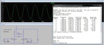
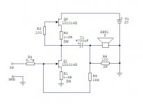
Q1 amplifies voltage and current (common Source mode) and Q2 is a CCS.
R5/R4 ratio sets the gain and R4 sets the Zin - don't use much higher value (up to 10k max) or you'll lose good treble. Of course, you signal/music source should be able to drive that Zin.
R6 keeps coupling cap C1 tied to GND when there is no speaker connected (to avoid panic about output DC offset).
Setting it right:
We want about 1A through JFETs (set with value of R2, start with 2R2 - lower resistance will give higher current) and about 10V (half of the V1) at the drain of Q1 (set with value of R1, start with 2R2).
If it happens that you have DC offset at input it means that your Q1 has a leaky gate but it's not a big deal, just use coupling cap at input (22u or so).
Don't forget to take good care about heatsinking Q1 and Q2 or, if you can't, lower the V1 to 15V or even 12V - it will still produce 1W at the output. If you have 16R speakers you can lower the current through Q1 and Q2.
PSRR is very good so no extra care has to be taken about power supply, simple CRC will do fine.
Attachments
Last edited:


Thanks Juma.
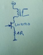
Although I must confess that I have a fetish for lightbulbs, so I may be inclined to use one instead of the upper Jfet 🙂
Although I must confess that I have a fetish for lightbulbs, so I may be inclined to use one instead of the upper Jfet 🙂
A question for Nelson: if you were to build a simple 1w amp witj Lu1014 j-fet, what would you do? I am thinking of something extremely simple, just for fun, something along the lines of Zen V8, but without the cascode, and maybe with a lightbulb 🙂
Will it work, or will it Pop? 😀
The problem with the Lu1014 is that I have not had good success making
it behave itself outside of a cascoded situation, and stopped trying after
a while.
But seeing as I have about 7000 of them, maybe I should take another
look.
I saw a German SRPP quite some years ago using a pair of LU1014 on 18V rails.
Could not find it anymore.
There is a Chinese website posting something similar.
But I could not recall whether the two are identical or not.
http://f1.hifidiy.net/forum/forumid_40/1004022234f3c255dd3fe97d50.jpg
Patrick
Could not find it anymore.
There is a Chinese website posting something similar.
But I could not recall whether the two are identical or not.
http://f1.hifidiy.net/forum/forumid_40/1004022234f3c255dd3fe97d50.jpg
Patrick
- Home
- Amplifiers
- Pass Labs
- FAOW