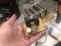
Would this be too big? 😉
looks perfect to put behind a horn tweeter and using output cap as 6db lowpass filter
🙂
Hi Michael,
Thank you for the schematic. Its sheer simplicity makes it irresistible 🙂
Instead of the Hammond, I guess one can use an appropriate lightbulb or maybe a Microwave oven transformer ...
Not so much the light bulb. That's a different amp. 🙂
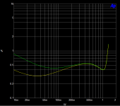
THD vs. Power
The yellow trace is PSU noise filtered. Possibly worth the effort to make a quiet regulated supply, but not strictly necessary. The switcher's fine too.
Actually, not too shabby. 🙂
The yellow trace is PSU noise filtered. Possibly worth the effort to make a quiet regulated supply, but not strictly necessary. The switcher's fine too.
Actually, not too shabby. 🙂
Attachments
Last edited:


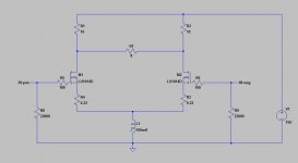
I don´t have any data or spice-model of the LU1014D, but one should be able to build something similar to this with normal parts.
Here is a balanced single end, fully DC-coupled one-or-few watt amp based on the LU1014D JFET.
Attachments
Last edited:
I have used the model posted by kekso22 with success (see post #26 of the thread below).
LD1014 SPiCE models
It is more realistic than the model provided by the manufacturer, epscially for the analogue region.
Patrick
LD1014 SPiCE models
It is more realistic than the model provided by the manufacturer, epscially for the analogue region.
Patrick
No. Assuming of course your source is clean of any DC.
Try to understand how it works, instead of copying blindly.
It is not so difficult.
Patrick
Try to understand how it works, instead of copying blindly.
It is not so difficult.
Patrick
I know the self biased common source (short but good explanation in Mr. Rothacher paper). If I´m copying blindy I would not ask the question about the need for input coupling capacitor. I´ll place them on PCB so no problem if source isn´t clean of DC.
Thank you.
JP
Thank you.
JP
If the source is not clean then you should clean it at the source (by cap or servo).
The circuit itself is (should be) Gnd referenced.
IMHO there is no need for an input cap (best cap is no cap).
(Unless you are making a product and want it to be idiot proof.)
And IMHO there is no need for a PCB, which is the whole point for its simplicity.
P2P is just fine, with or without a Vero.
Cheers,
Patrick
You might consider :
1) Build and test your proposed 120V Switcher (you will need a properly designed PCB for that);
2) maybe a break-off board added to that for the regulator of post #69 to clean off the switcher.
Cheers,
Patrick
1) Build and test your proposed 120V Switcher (you will need a properly designed PCB for that);
2) maybe a break-off board added to that for the regulator of post #69 to clean off the switcher.
Cheers,
Patrick
Michael,
I am sure you are aware that the IXTH6N50 is obsolete.
(Only a handful left at Mouser)
So perhaps you might suggest an active part for those who want to follow your steps.
Cheers,
Patrick
.
I think the IXTH6N50D2 is still active. That's the one I used.
I'm trying out some other stuff too tho. 🙂
That´s what I´ve planned.
I´m searching "cheap" >100dB loudspeaker or DIY plan with available châssis.
JP
I´m searching "cheap" >100dB loudspeaker or DIY plan with available châssis.
JP
> I think the IXTH6N50D2 is still active.
Part number search at the IXYS website returns no hits.
Patrick
Part number search at the IXYS website returns no hits.
Patrick
- Home
- Amplifiers
- Pass Labs
- FAOW