> It should be possible to move air more by convection
I did the math several decades ago. To get a blow like a $10 fan you need 30'-300' (10m-100m) chimney.
I'm under an airport approach and a chimney the height of the length of a football field seems unwise.
The short chimney assumed a temperature that is not good for Silicon. (Maybe 200c?)
I did the math several decades ago. To get a blow like a $10 fan you need 30'-300' (10m-100m) chimney.
I'm under an airport approach and a chimney the height of the length of a football field seems unwise.
The short chimney assumed a temperature that is not good for Silicon. (Maybe 200c?)
It took 5 mins to find it, but there is good info on the F5 thread about this, check post https://www.diyaudio.com/community/threads/f5-power-amplifier.121228/post-3893883 - Impressive cooling with a short "chimney" and no fan, it would be even more efficient with a fan.
Last edited by a moderator:
I created my own using a small PIC micro that had PWM and A2D.
The A2d reads the thermistor and the PIC converters reading to a PWM value.
With this method I can use cheap pc fans.
I added ports for two PWM connectors to drive two fans.
The A2d reads the thermistor and the PIC converters reading to a PWM value.
With this method I can use cheap pc fans.
I added ports for two PWM connectors to drive two fans.

I am considering the fins-to-fins scenario, for a certain amplifier. As the heat-sinks are actually made of metal, hence with electrical screening capability, I was wondering if it would be feasible to insert the following noisy items between the fins: Toroid transformer, 4,5 cm height, sideways; Rectifier board and main rectifier caps: 4,5 cm; PCB with ripple eater, module height 4,0 cm.It took 5 mins to find it, but there is good info on the F5 thread about this, check post #13945 - Impressive cooling with a short "chimney" and no fan, it would be even more efficient with a fan.
Basically, all these noise producing elements would be between the metal fins, in-between the fins, within the central section. In hope of achieving a screening effect.
But my question is the following: If this "chimney" is now 4,5 cm wider, it has a bigger cross section. Will such increased cross section of the chimney diminish the effectiveness of the chimney?
My heat singk profiles are cut 30 cm long. They are 19 cm wide, with fins 5 cm height.
If I arrange these vertically, I will get a chimney 30 cm high, 19 cm deep.
The "space" or "width" of the chimney would now constitute of:
a). 5 cm of inter-fin-area;
b). 5 cm of the sideways oriented components area;
c). 5 cm of inter-fin area.
Will the convection in such a wider chimney be comparable to the one as presented in the post aforementioned {without the b). } ?
Will the convection in such a wider chimney be comparable to the one as presented in the post aforementioned {without the b). } ?
I doubt it very much, I'm guessing it will not work... The only way is to try it and test, the the post I pointed to did.
...check post https://www.diyaudio.com/community/threads/f5-power-amplifier.121228/post-3893883 - Impressive cooling with a short "chimney" and no fan, it would be even more efficient with a fan.
Direct link to post 13945:
https://www.diyaudio.com/community/...-controlled-analog-no-pwm.336346/post-5930775
(hover the number "13945" and get the URL under it)
fin-to-fin ----- fins-outward
42.3C ----- ----- 44.9C
42.3C ----- ----- 44.9C
Yes, 2.6 deg C difference when heat is funneled to enhance convection.
This relative to a ~~23 deg C rise from ambient (20.1C). So about 12% better.
A $10 fan should give >10 deg C reduction, 100% better (but far louder).
Last edited by a moderator:
Just saw this thread, thank you Mark for the interesting work on the subject -I may end up using it.
My F6 is fine, except when the ambient temperature rises. I made my chassis, and used 4 ebay heatsinks, with the back up plan of adding a small fan to the fin end of each one, blowing towards the center of the base, where the mosfet is. It sounds great, but I can't help putting a hand on it every now and then to see how its doing. I think fans on the amp would be quieter than the AC 🙂
I was thinking of just on/off for the fan, using a close on rise TO 220 subminiture Bimetal Disc Thermostat, like a Sensata / AIRPAX 67F050P mounted on a heatsink. (I think they are available in 5 deg C increments.
Even if I throttle the fans down 40%, I think I could have the thermostat close at 50C, and it would cool things down enough. I haven't got as far as figuring out the details, whether powered from the PS or a separate wall wart, etc. I like the idea of a safety net, and it would let me dial the amp up it up a bit.
But Marks' approach is interesting too, as it allows the fans to start slow, and for most situations that would probably be enough. Another plus is that he has done the work of figuring it out 🙂
I am expecting a small, quiet fan in the mail for my SBC, might be a good choice for the heatsinks.
Michael
One of the better fans I have ,13dbnon pwm and still working silent from 2015 !!(h16)
blacknoise.com - Noiseblocker NB BlackSilentFan 120mm
blacknoise.com - Noiseblocker NB BlackSilentFan 120mm
This is a neat idea, and I'll need something like it to jam an F5 amp into a smaller enclosure. There is a real lack of chassis pictures and layouts around here! Any suggestions on possible layouts? I like using existing technologies: CPU cooler, like the classis Cooler Master Hyper 212, then possible a real big fan right on the inside top of the enclosure for hot exhaust like this big Phanteks 200mm (~8in) fan.
So I envision the MOSFETs with either own CPU cooler, then a big exhaust fan on the top. <shrug>????
https://www.hometheatershack.com/threads/behringer-ep4000-pics-fan-mod-etc.23528/
So I envision the MOSFETs with either own CPU cooler, then a big exhaust fan on the top. <shrug>????
https://www.hometheatershack.com/threads/behringer-ep4000-pics-fan-mod-etc.23528/
Big chassis, refrigerator fan.
Or put 0.4 to 2 uF/400V in series (or so), to slow a normal AC fan down.
Both can be controlled using thermostats or whatever you think will work.
Or put 0.4 to 2 uF/400V in series (or so), to slow a normal AC fan down.
Both can be controlled using thermostats or whatever you think will work.

Noctua fans are indeed delightfully quiet, although their price seems a bit steep. They're available in both 4-pin (PWM only) and 3-pin (PWM or analog) versions. If you wanted to use Noctua 12V fans while simultaneously insisting upon an all-analog controller, in a First Watt amp running from a standard First Watt 23V supply, your options include: (a) use a 24V all-analog controller and simply connect two Noctua fans in series; (b) obtain a 12V all-analog fan controller and power it from a 12V regulator; (c) draw up a new and different design target Volts-vs-Temp curve, similar to "Figure 2" in post 1 above, with your new desired slope and Anchor Point, but which tops out at 50% instead of 100%. Then tweak component values until you get that design target curve; (d) and more.
A snippet regarding 12v operation
What an interesting, (and for me) educational, project. Thank you for investing your time and knowledge on this. Much appreciated.
Is there any simple way to modify this circuit for 12V fan?
Also any of the IRF9510 can be used?
A word of caution: this circuit contains so few parts, that each individual part has an effect upon several different aspects of circuit behavior. In other words, everything interacts. Strongly. When designing or redesigning a circuit like this one, it takes a lot of tweaking and adjusting and juggling to get the circuit to work well. Fortunately for you, I have already performed this miserable job; it took me about a half a day to get it completely dialled in. The schematic in Figure 3 works nicely ... but only for THIS supply voltage (24V), and only for THIS choice of thermistor, and it only implements one specific design target curve of Temperature-versus-FanVoltage (shown in Figure 2).
If you want to modify the circuit to operate at a very different supply voltage, or to use a different thermistor, or to hit a different design target T-vs-F curve ... then you will need to tweak and adjust and iterate and juggle component values, to get your new circuit working and meeting your new specifications. It will take effort. Do I know of any time saving procedure(s) for this? Not really; all I can suggest is to thoroughly explore and experiment and keep good notes. And don't forget to have fun!
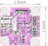
However if you want to use a not-fully-insulated MOSFET just make sure it has a similar gate threshold voltage, and that its dataseet safe operating area actually includes a curve for DC, and the fan current is way waaaaaay below that curve.I like the fact that [FQPF11P06] is in a fully insulated TO-220FP "full pack" package, and requires no insulator between MOSFET and heatsink.
Attachments
See #30 above.
AC fans are more reliable, the DC fans have a circuit for DC to AC, those are solid rotor squirrel cage motors without brushes.
So basically a low voltage AC fan, the mains versions are generally more reliable, there is a bigger choice as well, regarding flow rates, noise, and flow velocity.
Just find a low noise AC fan. the biggest that will fit, and reduce the speed in a convenient way.
Yes, for 65W cieling fan speed controllers they use 4 / 4.5 uF for slow and medium.
I suggest you try several values until you are satisfied with the performance.
Or simply buy a ready regulator, those are cheap, within 100 Rupees!
I paid 28 for a BT131 based unit the size of a 5 A switch, Hyderabad, Troop Bazaar, 2019.
Bigger one was about 50, for fitting on the switch board on top of sheet.
Capacitor models also are in similar range...see online to get idea of what is available, and price.
See this: (just a random net search link, not connected to me)
https://circuitspedia.com/ac-dimmer-fan-regulator-circuit/
- Home
- Amplifiers
- Solid State
- Fan inside audio chassis: variable speed, temperature controlled, analog - No PWM