There are certainly situations where it would be preferable to build a separate power supply and swap different amp chassis. However, the size of the heatsinks will be determined by the total bias current per channel (split between one or two devices per rail) multiplied by the rail voltage.
Modern electrolytic capacitors have become much more reliable than those used even 10 years ago. Caps with an 85 °C rating may be safely used inside any of the amps that we are likely to build on this forum, provided that they are properly rated for voltage.
I recommend using caps with at least 35V rating, even for 23V power rails. Better still, use capacitors with 50V rating for best longevity, especially if you plan to be pushing the thermal limits. This was basically the recommendation of a reliability engineer that I used to work with.
My thought was that the heatsinks may not be as much of a limiting factor if you can run them at say 65 degrees celsius instead of 50 degrees.
You can get the rubber puck-style feet that you see on pro equipment that are 1"-1.5" tall. They are cheap and much better than the plastic feet the DIYaudio chassis comes with.
I happen to like these in particular:
https://www.parts-express.com/4-Pack-Rubber-Cabinet-Feet-2.5-Dia.-x-1-H-260-7502?quantity=3
It needs to be supported on 3/4” wooden strips to help with airflow around the heatsinks.
You can get the rubber puck-style feet that you see on pro equipment that are 1"-1.5" tall. They are cheap and much better than the plastic feet the DIYaudio chassis comes with.
I happen to like these in particular:
https://www.parts-express.com/4-Pack-Rubber-Cabinet-Feet-2.5-Dia.-x-1-H-260-7502?quantity=3
one last thought. There is the little thermal switch that Randy has in the BOM of his alephs. You can use those in case say the AC goes out while you're gone.
THERMOSTAT 70DEG C SPST-NC 1862-1126-ND
THERMOSTAT 70DEG C SPST-NC 1862-1126-ND
Starting up the new channel boards (w/ IXTQ75N10P) resulted in un-scheduled release of magic smoke from one of my diamond buffer input stages.
I am carefully re-evaluating the circuit construction and layout of both diamond buffer boards until I know I will not repeat the problem.
I am carefully re-evaluating the circuit construction and layout of both diamond buffer boards until I know I will not repeat the problem.
I found two issues with the board that smoked.
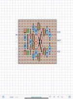
One was a design problem that crept into the layout. One of the voltage references was reversed. The corrected layout is below.
The second problem was a small solder bridge on the underside of the vero board. I’m still cleaning up & replacing fried parts.
One was a design problem that crept into the layout. One of the voltage references was reversed. The corrected layout is below.
The second problem was a small solder bridge on the underside of the vero board. I’m still cleaning up & replacing fried parts.
Attachments
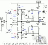
The schematic is a little different from Austin. I have eliminated R8 and C4. Instead I use Base resistors of 10 Ohms in front of Q5 and Q6. Q5 and Q6 have been changed to TTC004B and TTA004B.

I got both channels rebuilt after the adventure with the input stages.
Power on testing one channel at a time revealed that the input threshold voltage of the IXTQ75N10P Mosfets exceeds what can be achieving with three green LEDs as the voltage reference. I was only able to see 1.4A of bias current, which I don’t consider sufficient for what I want to do with the amp.
Next up is trying a different configuration for the voltage references that will let the Mosfets run nice and hot.
The higher threshold voltage requirement of the IXTQ75N10P may rule them out for some. I still like the other parameters, and hope that they may be useful replacements for the discontinued FQH44N10.
Perhaps adding another LED to the string (4 leds) ...?
After your comments about the FQH44N10 shortage, I went looking for some more - alas, not many around from reputable sources at all.
After your comments about the FQH44N10 shortage, I went looking for some more - alas, not many around from reputable sources at all.
jameshillj,
What MOSFETs do you have in place now?
The IRFP150 are an option too.
TA,
Did you try playing some music with the new MOSFETs in place? Everyone might not be going for higher bias points and it would be good to know how they sound to you subjectively at 1.4A bias.
What MOSFETs do you have in place now?
The IRFP150 are an option too.
TA,
Did you try playing some music with the new MOSFETs in place? Everyone might not be going for higher bias points and it would be good to know how they sound to you subjectively at 1.4A bias.
I haven’t tried playing music with the new Mosfets in place. It’s certainly possible that 1.4A bias might be sufficient for moderate listening. After all, the M2x is biased at 1.3A.
I have some extra LEDs available to increase the number in the string. I am inclined to increase the reference voltage first, then experiment with different bias currents. My LED strings are giving me 5.86V, which suggests they could use more current.
For those playing the game at home, three LTL4231 LEDs can get close to 6.0 V with sufficient current through the string. Try a dropping resistor of 3.01k above the string.
My F6, (Dual mono power supplies) with FQH44N10
Runs at 1.4 amp bias and sounds good to me.
I tried higher bias but my old ears could not hear much difference, so for peace of mind. and cooler operation I lowered it again.
Runs at 1.4 amp bias and sounds good to me.
I tried higher bias but my old ears could not hear much difference, so for peace of mind. and cooler operation I lowered it again.
Sorry "Mt T",
I'm still using both the 'standard' IRFPs - pretty boring, I know, but happy with the sound driven by the Salas reg supply (Torroidy metal, LT4320 bridges, T-Network caps, etc) into the Betsy Alnico FR >160Hz on an Open Baffle (Martin King folded version) - went a bit 'nuts' with the fancy resistors and caps! And playing with the IPS7 + Burson V6 for the input stage and waiting for more supplies of the recent diyA FE input stage but might just try your verobrd version too.
The Room has added 'leanfusers' (1D diffusion) for a rather 'immersive/all round' sound - source mainly from Auralic Altair G1 Steamer.
I tried leaving the three green LEDs in place and reduced the dropping resistors to 3.01k. The LED strings produced a reference voltage of 5.95V. This indicates that the LED strings have effective voltage regulation.
One channel was able to achieve a bias current of 1.5A. The other channel could only reach 1.37A.
It will be necessary to boost the voltage higher to have sufficient margin to achieve the desired bias current.
One channel was able to achieve a bias current of 1.5A. The other channel could only reach 1.37A.
It will be necessary to boost the voltage higher to have sufficient margin to achieve the desired bias current.
can you post a schema of this Board?I found two issues with the board that smoked.
One was a design problem that crept into the layout. One of the voltage references was reversed. The corrected layout is below.
The second problem was a small solder bridge on the underside of the vero board. I’m still cleaning up & replacing fried parts.
I have not drawn the diamond buffer schematic yet. Ideally this would be captured in a PCB layout tool.
For now, the VeroBoard layout defines the circuit. This is actually a common technique for builders of DIY guitar effects pedals. I built a few different bass effects pedals for personal use before branching into alternate input stages.
For now, the VeroBoard layout defines the circuit. This is actually a common technique for builders of DIY guitar effects pedals. I built a few different bass effects pedals for personal use before branching into alternate input stages.
IXTQ75N10P?
Yes!
I just had an early morning listening session with the new Mosfets and bias current circuitry. These Mosfets require a little more care and feeding relative to the others that I was using. They are absolutely worth the extra effort.
More details to follow..
Yes!
I just had an early morning listening session with the new Mosfets and bias current circuitry. These Mosfets require a little more care and feeding relative to the others that I was using. They are absolutely worth the extra effort.
More details to follow..
This version of the F6, with IXTQ75N10P output Mosfets and a number of other modifications seems to be the one that drives the big Vandersteen 3As to reach more of their full potential. More than the M2x, which still does a very credible job, and more than the earlier F6 configuration with the FQH44N10 devices in the output. The stage extends taller and deeper, with more detail around each instrument, better control of all frequencies, especially deep bass.
I had to take a different approach to the voltage sources that are part of the bias current circuitry. I had a few difficulties constructing strings of four LEDs for each of the output devices. In the end I used a simpler combination of an LM329 plus an old style 5mm red LED. The voltage sources with this combination provide a more steady bias current for the big Mosfets, and are much easier to build. Final bias current has been set to 1.85 A.
I had the LM329 references from my original F6. Adding a red LED above the reference increases the total voltage to 8.5V, given 5 mA current through the pair. The red LEDs contribute 1.5V to the pair and are dimly lit in operation. Overall thermal coefficient of the LM329 + LED seems to be slightly negative.
- Home
- Amplifiers
- Pass Labs
- F6 Illustrated Build Guide