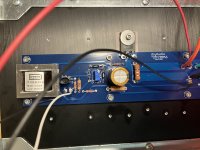
Just started.How far are you into the set up / biasing process?
tungsten, I’ll check that now.
Is there a scenario where the voltage on the source resistor would switch from positive to negative?
I had everything set last night but the leds were not working. I switched them this morning, adjusted the bias again, it was still pretty close to last night, then I left it for about 5 minutes. When I came back, my meter showed -.505, both channels. I backed the bias pot all the way out until it started clicking, then screwed it back in and now the values are positive again?
It’s when I switch the leads around, it gives me the same value positive and negative. I didn’t know it would do that.
Last edited:
re: LEDs, one of the LEDs (can't remember which board is which)... is on the positive rail, and one is on the negative rail. You're definitely not alone installing one of them backwards.
However, if one of them was working the previous day... and then stopped working... that is a slight concern, unless you switched the wrong one around, and now both are not working.
What (if anything) did you do in the middle?
Yes, if you swap the leads around, you should get an equal and opposite reading. It sounds like that is what you did. Nothing changed in the circuit, but you swapped your black and red probe. You can do that with any DC voltage reading. In the case of the bias voltage reading across the resistor, just use the absolute value. The current (I don't think unless there is a big problem) will never go in the unintended direction. Bias it back up if you haven't already.
Cheers!
As always - I'm learning too... so, take everything with a grain of salt and/or wait for a more experienced member to chime in. I typically wait a bit to let them chime in first, but I feel pretty confident about this one.
However, if one of them was working the previous day... and then stopped working... that is a slight concern, unless you switched the wrong one around, and now both are not working.
What (if anything) did you do in the middle?
Is there a scenario where the voltage on the source resistor would switch from positive to negative?
Yes, if you swap the leads around, you should get an equal and opposite reading. It sounds like that is what you did. Nothing changed in the circuit, but you swapped your black and red probe. You can do that with any DC voltage reading. In the case of the bias voltage reading across the resistor, just use the absolute value. The current (I don't think unless there is a big problem) will never go in the unintended direction. Bias it back up if you haven't already.
Cheers!
As always - I'm learning too... so, take everything with a grain of salt and/or wait for a more experienced member to chime in. I typically wait a bit to let them chime in first, but I feel pretty confident about this one.
I had them backwards, they’re both working now. Thank you for the suppport and encouragement.
I'm looking for help troubleshooting my F6. It's pretty much a stock build, No diode changes or LED mods.
Q1 on one of my channels heats up to scorching hot if I allow any amount of current to go through the amp. Meanwhile Q2 stays cool and passes the signal happily. I've replaced Q1 with a known good IRFP240 with no luck, same issue.
Something has to be wrong somewhere else and I feel like I've checked every component value I can with my multimeter and all are in spec and matching the opposing channel as far as I can tell. Signal looks good at R11. I replaced the capacitor at C1 no help there either. Can someone help me troubleshoot this?
Thanks in advance,
JoJo
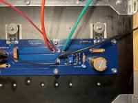
Both offsets are at 2.7k. Here's a pic, apologies for the dust, it's been sitting on the bench for a while and i'm finally getting to it

Have you checked (measured) your offset pots?
Do not assume which direction they are adjusting, or even that both are the same.
Do not assume which direction they are adjusting, or even that both are the same.
Dennis,
The story is this is one of my first kit builds when I was getting started and I got it up and running and it sounded good but after a few days the left channel catastrophically burnt up. Turns out I had swapped q3/q4, I'm amazed it worked in the first place. I bought a new board and new transistors. Transplanted what I could and replaced the out of spec components. I ended up needing to replace the JT123 as well. I've put a lot into getting this back off the ground and am really looking forward to hearing it shine again. During the time it was out of commission I got more into the hobby and have added a bunch of equipment to my bench and learned a lot about audio circuitry and amp troubleshooting and have applied all I know to figuring out whats going on here but there is still something i'm not seeing.
I'm using 5.1v zeners in both places.
With 40w DBT current limiting the power input I see ~130mv dropped across both R1 and R2. I'm hesitant to take it "off the leash" for long because Q1 starts dissipating about 120W if I connect the power supply to unlimited mains. But I can do that briefly to take a real reading if it'll help.
ColinA123,
I'm measuring 3.3k ohms on either side of z1 for both channels. LMK if you want me to remove the pot and test it out of circuit.
Last edited:
Your pcb looks to be very close to the heatsink. Are there standoffs between the pcb and heatsink. Be sure that there are no shorts between the pcb and the heatsink.
Measure the Vgs of the mosfets with the power on and DBT in place. Is the Vgs around 4V at both mosfets when the voltage across R1 and R2 is 130mV?
Turn the pots until the voltage across R1 and R2 is zero. Are you able to zero the voltage? What Vgs at the mosfets?
If the voltage across R1 and R1 can be zeroed, set them at zero and remove the DBT and power up. What are the voltages across R1 and R2? Vgs?
Ben,
No observable shorts to the heatsinks, Using the standard standoffs that come with the kit.

Was able to zero both Resistors.
Off the DBT I got the following:
R1 30mv
R2 40mv
Q1 Vgs 3.7v
Q2 Vgs 3.8v
Current climbed up to 100W before I put the DBT back in line. Much slower this time though.
Thanks for your help!
No observable shorts to the heatsinks, Using the standard standoffs that come with the kit.
Was able to zero both Resistors.
Off the DBT I got the following:
R1 30mv
R2 40mv
Q1 Vgs 3.7v
Q2 Vgs 3.8v
Current climbed up to 100W before I put the DBT back in line. Much slower this time though.
Thanks for your help!
- Home
- Amplifiers
- Pass Labs
- F6 Illustrated Build Guide

