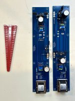
F6 & F4 boards have arrived, these are better quality than what comes in most amps I've purchased. I got the Jensen transformers from Cable Solutions in the US since the DIY store is out of stock.


Have you looked at the "zenner mod" or the possibility of using three green leds for bias?
Either of these is worth doing over the original design (Note, I don't know what ships with the current kit.)
R7 and R8 to something like 3K3 (from 10K)
Then Z1 and Z2 to 6.2 volts OR three green leds in series replacing the zenners.
These are much simpler to do on first build rather than swapping later. 🙂
I also like the (now discontinued) FQH44N10 Mosfets. They happen to like higher voltage and bias current. I have taken advantage of this. Power rails are +/– 26.5V and bias is 1.95A, as recently re-adjusted and confirmed.
TA,
Any other MOSFETs you suggest in place of the FQH44N10?
The closest part, at least on paper, that I have found so far is the IXTQ75N10P. I just ran across this one while doing another search of available parts to substitute for the FQH44N10. It has favorable transconductance, input Gate capacitance and Gate charge numbers, plus it has a power dissipation rating of 360W. Device characteristic curves look good overall. Again, this is on paper.
I am going to order a tube of these from Mouser and give them a try with my new speakers.
They might also do well in higher voltage versions of the good old ACA.
I am going to order a tube of these from Mouser and give them a try with my new speakers.
They might also do well in higher voltage versions of the good old ACA.
Funny that you ask 😉
Yes, I have a tube of 24 sitting on my bench. Those and a pair of bare F6 PCBs plus other parts are waiting to be assembled. The Jensen transformers are going to be re-purposed from a pair of Bulwark input stages, a fun experiment that has run its course.
I recently readjusted the bias current in the F6 (FQH44N10 version) to 1.95 Amps per device. It’s running a bit hotter than before, on the edge of wanting to remove my hands from the heatsinks after 10 seconds. Sounds great with the big Vandersteens. Gives a little more of everything vs the M2x. Which is also how the 3As compare to the 2Cs. The F6 really has a tighter grip on the bass.
The new IXTQ75N10P version will take a couple days to build. I plan to make a couple small changes to accommodate the different Mosfets.
Good to see that you are experimenting... by any chance do you have any measurement gear? It would be very interesting to see the changes in the harmonic profile as you change the bias point and try different output devices.
Look forward to hearing about your impressions with the IXTQ75N10P. A couple of days is an aggressive timeline, but hey, the parts count is low, you know the design very well, and you are also a skillful builder. 🙂
Have fun!
Look forward to hearing about your impressions with the IXTQ75N10P. A couple of days is an aggressive timeline, but hey, the parts count is low, you know the design very well, and you are also a skillful builder. 🙂
Have fun!
The big Vandersteens really love the high-bias F6.
More bass. More control. Better instrument definition and separation.
Those are the things that stand out.
More bass. More control. Better instrument definition and separation.
Those are the things that stand out.
I know you have posted a schematic of your diamond buffer setup in the past. I tried digging it up to no avail. Do you still have it handy?Work in progress..
I need to build a new pair of Diamond Buffer boards for the input. I like that one for driving the big Mosfets through the signal transformer.
This is the strip-line (vero) layout that I use. It is a tweaked version of the M2x Austin input stage. It works from the +/- 26.5V rail from my power supply. I tie it into the JFet buffer pads.

I thought i had a good stash of parts to finish a pair of the buffers, but that turned out not to be the case. So another order from Mouser is on the way..
What about using the diyA FE as input stage, maybe set to +6dB gain and the 'positive feedback' to 'guild the lily' ...! The Powertron 3Watt resistors (Manganin material) are quite a change-up in the sound but the cost has gone ridiculous now
I will probably stay with unity gain buffers. The other one that I might try is the high voltage, high current OPA551 opamp. And the OPA445. Both of those worked well in my DIY VFET lottery amp via the Marauder front end.
These could probably be applied to the F6 with a simple scheme like the M2x Tucson input stage.
These could probably be applied to the F6 with a simple scheme like the M2x Tucson input stage.
The Diamond buffer that I am using could be adjusted to run on even higher voltage rails. The 10k resistor in the middle of the vero board will be increased to 15k when I finish the build. The TTA004B / TTC004B parts are better suited to higher voltage operation than the M2x Austin.
If one wished to keep the original JFet front end (K170 / J74), they would need to be cascoded to protect the J74.
The power rails in my F6 are only a little higher than standard (26.5V vs 23V), The limiting factor is heat being dissipated by the power Mosfets in the output stage of the amp. The FQH44N10 devices have a higher power dissipation rating than IRF240s. Even so, at the higher bias current that I like to use, this amp runs pretty hot. It needs to be supported on 3/4” wooden strips to help with airflow around the heatsinks. The IXTQ75N10P devices appear to suitable for higher power dissipation.
ZM likes to run hotter amps like this on a platform that he calls a babysitter. It uses fans to increase airflow. I’m on the edge of needing to build one.
It is mainly the caps that need the cooling right? Not so much the Mosfets. They seem to be able to cook pretty good and prance along just fine. If you had an external power supply, would the rules change for how hot the devices could get?
https://www.diyaudio.com/community/threads/i-made-an-aleph-5.372708/#post-6666318

https://www.diyaudio.com/community/threads/i-made-an-aleph-5.372708/#post-6666318
Mikerodrig27,
you stop with that separate PS talk. 😏 Now I'm hankering to do such a thing so I can have swappable output sections. I've been staring at the quad of F6 boards I pulled to install the F4s, thinking that it'd be fun to listen to them again. Way too much work to surgery them back in. And I have a quad of M2x boards wanting to be built and listened... The horror.
you stop with that separate PS talk. 😏 Now I'm hankering to do such a thing so I can have swappable output sections. I've been staring at the quad of F6 boards I pulled to install the F4s, thinking that it'd be fun to listen to them again. Way too much work to surgery them back in. And I have a quad of M2x boards wanting to be built and listened... The horror.
Yeah, I get it. I just built some Aleph 2's for a friend and now I am smitten by them. So I am thinking an Aleph X with jfets is in my future... Similar sound while still experiencing something new.
The external power supply may save you a few bucks if you are building several amps in different cases. But then you are buying a case for every amp 😱. I don't think there is an end to this.
The external power supply may save you a few bucks if you are building several amps in different cases. But then you are buying a case for every amp 😱. I don't think there is an end to this.
- Home
- Amplifiers
- Pass Labs
- F6 Illustrated Build Guide