In an electrically clean environment with no interference, braided cables will work. Also speaker sensitivity is a factor. With speakers of lower sensitivity, a noisy system may seem quiet.
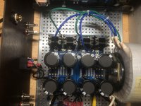
Inside an amplifier case with a large power transformer present, I prefer to twist the wires to minimize to loop area as much as possible. I do that because I have 103dB sensitive speakers so I want to do my best to minimize noise. Nothing is better than no hum or buzz from my speakers during quieter moments or when no music is playing.
Now some may have less sensitive speakers so a noisy amplifier may not show itself. However I believe that amplifiers should be built to be as quiet as possible, even if the speakers to be used with them are not very sensitive. That way it is ready for the possibility of more sensitive speakers in the future.
I never knew that about braiding vs. twisting, Ben. Thank you for the thorough and thoughtful explanation.

Just to be sure - I am probbaly over cautious - I have a light bulb wired into my chord from the socket - the picture shows my multimeter clips on positive and negative on the power supply - I followed the picture in the build guide with the "safety" cap across the two line inputs -- It showed the CL-60 as basically tying the two transformer leads, parallel inputs, together this seems strange to me since it is bridging two parallel circuits but I guess it works.
I saw the post about Audio ground v chassis ground -- not sure how clear the picture is but I have ground from the IE Socket connected to a bolt on the chassis as well as the ground wire from the transformer - I also have a CL-60 between the ground in the center on power supplly (the same ground point as goes to each channel) I am concerned about this last ground I may be mixing chassis and audio Ground. Isn't this a star ground?
I saw the post about Audio ground v chassis ground -- not sure how clear the picture is but I have ground from the IE Socket connected to a bolt on the chassis as well as the ground wire from the transformer - I also have a CL-60 between the ground in the center on power supplly (the same ground point as goes to each channel) I am concerned about this last ground I may be mixing chassis and audio Ground. Isn't this a star ground?
Attachments
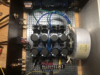
So far so good. The CL-60 between audio and chassis ground is known as a loop breaker. It does make a DC connection, but keeps the two grounds somewhat isolated. The audio ground at the center of your PSU is now the point for a star grounding scheme. Best to attach the speaker negative terminals to this star ground.
It will make things easier if you power up one channel at time. Use two multimeters – one to measure Iq (as voltage across one of the source resistors), and the other to measure DC offset across the speaker terminals. Do not hook up a load to the speaker terminals yet.
It will make things easier if you power up one channel at time. Use two multimeters – one to measure Iq (as voltage across one of the source resistors), and the other to measure DC offset across the speaker terminals. Do not hook up a load to the speaker terminals yet.
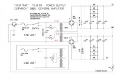
Won't, like I have with the multimeter on v++ an v-- points, tell me if I am getting 20 volts DC out of my power supply and then the dual meters would measure the Iq (what is the source resister?) and the DC offset on my amplifier boards
^ NO, the way you have connected your multimeter test leads is not very useful for making the measurements you need. Go back and re-read the build guide.
Any harm in using 110 ohm 3 Watt for R3 ? I have some spare ones and will for sure be using 110 ohm for R11/12 as mentioned in the build guide.
I'm still confused about my power supply, it is the Universal Power Supply board - I plugged it in with the light bulb and the light bulb glowed and faded out - My LED's lit up -- seems good to me
The build guide says put the multimeter across the .47 ohm source resistor
I have 4 .47 ohm rsistors on each side and an LED drop resistor - I tried the multimeter on first and then the last resistor on each side it ends up abou t.001
I tried different resistors and there is minimal voltage. The light bulb quit working after the first time but I assume this is because the capacitors are still charged since the LEDs remain on. After a longer wait the light bulb lights and fades
It seems to me that since I should be putting out 18- 20 volts to my amp boards I should get 18-20 colts on v++ and ground - but again I get almost nothing.
I must be missing something. I want to be sure my power supply is OK before I start connceting and powering up my amp boards
That’s for when you set bias.
Put one probe of your DMM on ground on the PSU board or connect to chassis.
Then put your red probe on V+, check for around +24V and on V- with red probe you should get around -24V.
Put one probe of your DMM on ground on the PSU board or connect to chassis.
Then put your red probe on V+, check for around +24V and on V- with red probe you should get around -24V.
That worked exceept I got 29.5 and -29.5 DC -- I'm using a 20 volt Transformer -- I think 18 is suggested but someone told me this would be OK -- DO I need a resistor somewhere? Or can I handle the extra voltage by adjusting the bias etc.
I would think the voltage would sag a bit once you hook up the F6 boards.
I just finished two M2x amps that had +-27V until I added the boards and the voltage dropped to 24.5V.
I just finished two M2x amps that had +-27V until I added the boards and the voltage dropped to 24.5V.
I Looked around and found that dropping the voltage isn't as easy as adding a resistor and a few volts either way may not be a big deal so I think I'll move on
Yes, the voltage will drop quite a bit once the channel boards start drawing current. The transformer, rectifiers and resistors will all have a voltage drop. This is normal.
That worked exceept I got 29.5 and -29.5 DC
Those voltages are perfectly fine...continue on with your project!
tbrooke,
When you test the power supply only, the only load present is the bleed resistor and the LED on the board. If you are using the standard diyAudio power supply, the bleed resistor is typically 2.2K which will only draw about 10mA or so. So if the dim bulb tester glows bright and then fades out, that is a good sign as the 10mA current is not enough to light the bulb. So your power supply is not shorting.
Next you can test the amplifier board. Important - test only one board at a time!!
Follow 6L6's instructions on page 1.
I use the trusty old mains Variac to initially slowly charge up the supply with a 16R/50w load resistor connected on each rail - the variacs even come with earth leakage switches these days and sometimes also with meters.
You can see any problems before the voltages get to damage anything.
You can see any problems before the voltages get to damage anything.
- Home
- Amplifiers
- Pass Labs
- F6 Illustrated Build Guide