did anyone try this?

By the way, did anyone try this (from ebay or other places)?
”6pcs HSS 6542 Titanium Coated M3-M10 Combination Drill Tap Bit Set 1/4 Inch Hex Metric Deburr Countersink Bits”
It seems to be an interesting ideea, but I don’t know about the resistence in time of these pieces.
^ Those look like a disaster waiting to happen. The drill feed rate through the material is unlikely to be the same as the thread pitch X rpm.
Best to keep the drilling and tapping operations separate, especially for the typical hand tool or drill press user.
Best to keep the drilling and tapping operations separate, especially for the typical hand tool or drill press user.

Unfortunately, the wife entered the man cave one day and demanded a major tidying up operation was required. Happy wife = happy life = many more amps to build in peace! Shhh... She doesn't know the secret messy spots! ;-p

An externally hosted image should be here but it was not working when we last tested it.
It sings beautifully !
Thanks Nelson Pass and everyone here, for these to be possible.
Now the hardest part....to make a chassis for it.
Thank you very much for your advices; very useful for me.
As a conclusion: Certainly I'm also very interested in this UMS.
So, for the moment we are 4. Another one person and this good hope to become reality.
Pity i did not follow this thread proper. I just ordered a 4U/400 chassis from the store yesterday for my M2. Would have been nice if it had UMS heatsinks.
Regarding bias settings...
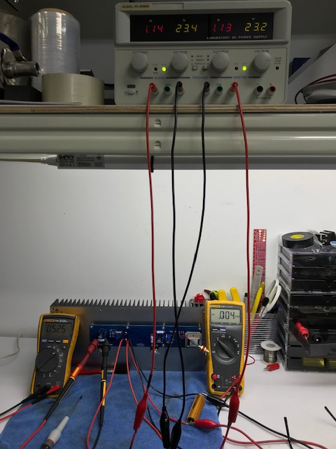
I ran the F6 for 4 hours yesterday. bias set at 0.52v for both channels, verified that it is still there after another hour.
This morning, i let it sing for an hour, check the bias, both channel went up to 0.64v, however nothing bad seems to happens, still sings beautifully.
I suspected that the ambient temp may have caused the bias drift, coz i didn't switch on the aircon.
Is this normal ? It is safe to leave it bias at 0.64v ?
That’s fine. You’ll need to change it once you have a chassis, bit a bit of drift is normal, particularly if stable.
Unfortunately, the wife entered the man cave ...
By the way, an interesting woman; I hope it is not the only one in the world! https://youtube.com/watch?v=7ylVRqfKfvM 🙂
By the way, an interesting woman; I hope it is not the only one in the world! https://youtube.com/watch?v=7ylVRqfKfvM 🙂
Interesting.
Regarding the comments on that video; those are the very reasons other people have a general dislike of audiophiles and make fun of them (audiophools). There's always a fool who knows better.
Swapping front & rear panels
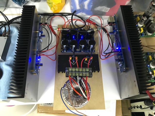
I'm in the process of doing a "mental build" of the F6, while I slowly gather the parts together. I see the advantage of keeping the power transformer away from the input transformers. I also like the concept of keeping all AC power wiring close to the IEC socket. It seems that by simply swapping the front panel with the rear panel so that it is the opposite of the configuration in the Build Guide, that this kind of layout would be possible. Is there something in the design of the diyAudio Deluxe 4U chassis that would prevent this method of assembly? One of the shortcomings, of course, of mental imagery is that you can't just inspect the chassis to get a quick answer. Can anyone help, please?
I'm in the process of doing a "mental build" of the F6, while I slowly gather the parts together. I see the advantage of keeping the power transformer away from the input transformers. I also like the concept of keeping all AC power wiring close to the IEC socket. It seems that by simply swapping the front panel with the rear panel so that it is the opposite of the configuration in the Build Guide, that this kind of layout would be possible. Is there something in the design of the diyAudio Deluxe 4U chassis that would prevent this method of assembly? One of the shortcomings, of course, of mental imagery is that you can't just inspect the chassis to get a quick answer. Can anyone help, please?
Wouldn’t that be the same as flipping the F6 boards, so the F6 transformers are at the front of the chassis ?
Great; thanks for the confirmation! I'll check that box off in my mental build manual, and move on to power supply layout. I'll shout out when I hit another snag. It's good to know you guys have my back!
Remember to do the Zenner mod as you build.Great; It's good to know you guys have my back!
Attachments
Yes, definitely will do the Zener mod.
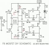
BTW - I have not seen any mention of applying separate V+ and V- regulation for the input buffer stage. Does anyone know what benefit, if any, there might be in running those FETs at, say, +20V/-20V regulated (using the existing 23V supplies as the source voltage for the regulator circuits)? That would, of course limit the peak voltage that can be applied to the MOSFET gates through the transformer. Would that be a serious reduction in peak output power?
BTW - I have not seen any mention of applying separate V+ and V- regulation for the input buffer stage. Does anyone know what benefit, if any, there might be in running those FETs at, say, +20V/-20V regulated (using the existing 23V supplies as the source voltage for the regulator circuits)? That would, of course limit the peak voltage that can be applied to the MOSFET gates through the transformer. Would that be a serious reduction in peak output power?
So, got sound from my f6 a couple of days ago, but during my first listening session I noticed I had a hum..
F6 is built extremely close to the 6L6 build guide, only difference was unshielded input leads. Even putting my hand close to the wires made sounds at the speakers. So i changed to some "double shielded" car stereo lead. It was abit better. But when nothing is connected, if i touch the input lead on top of the insulation, or even come close to i with my hand, i get louder hum and ticks in the speakers. Also when i touch the chassis.
Its a bit better when i connect my dac, and even better when i connect my ipad. Then only a mild hum remains, no contact noises on chassis or cable. But its still annoying and i can hear it from my sitting position.
So, my ground is chassis via CL60 to gnd in on psu. I have 4 filter resistors on the psu, and 15.000 uf capacitors. I have tried with and without safetyground. Bought a snubber, but no resistor (should be 10 ohm?), so havent tested. Toroid is toroidy, but not the potted one. I have tried different position for the toroid, even outside the case, no difference. Tried rectifiers mid air .. hm what next.
Also .. as an added bonus.. I did some tidying of the leads while power was on (yes, genious i know) , and accidentally pulled out the V- lead from psu to one of channels. There was not so nice sounds , and maybe a little smoke. And now that channel has more hum than the other Any adea as to what happens when that lead is pulled. I suspect input JFETs got some flack.
Any pointers as to what to check next appreciated! 🙂
F6 is built extremely close to the 6L6 build guide, only difference was unshielded input leads. Even putting my hand close to the wires made sounds at the speakers. So i changed to some "double shielded" car stereo lead. It was abit better. But when nothing is connected, if i touch the input lead on top of the insulation, or even come close to i with my hand, i get louder hum and ticks in the speakers. Also when i touch the chassis.
Its a bit better when i connect my dac, and even better when i connect my ipad. Then only a mild hum remains, no contact noises on chassis or cable. But its still annoying and i can hear it from my sitting position.
So, my ground is chassis via CL60 to gnd in on psu. I have 4 filter resistors on the psu, and 15.000 uf capacitors. I have tried with and without safetyground. Bought a snubber, but no resistor (should be 10 ohm?), so havent tested. Toroid is toroidy, but not the potted one. I have tried different position for the toroid, even outside the case, no difference. Tried rectifiers mid air .. hm what next.
Also .. as an added bonus.. I did some tidying of the leads while power was on (yes, genious i know) , and accidentally pulled out the V- lead from psu to one of channels. There was not so nice sounds , and maybe a little smoke. And now that channel has more hum than the other
Any adea as to what happens when that lead is pulled. I suspect input JFETs got some flack.Any pointers as to what to check next appreciated! 🙂
- Home
- Amplifiers
- Pass Labs
- F6 Illustrated Build Guide