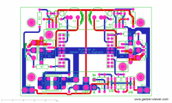

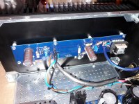
This layout has provision for P3 and P4 for variable 2nd harmonic. Do I have to short all 3 pot pins to bypass it? I currently have it only connected so that it doesn't bypass source degeneration resistors. If I connect all 3, it will bypass those.
Find a pic that shows bypass of P3/P4 here:
Post #18 of F6 GB thread
Thank you Mighty ZM - is it the 3A currrent at 4V VGS that is the problem? I don't know what the important statistics are which is how I ended up buying those in the first place but no matter ... I've replaced them with IRFP240 now and still have cold fets with no current going through source resistors.
I have taken voltage readings across the LED string and see 5.54V on both sides, is that too low? These are supposed to be 3.4V LEDS but that is now in parallel with 5K pots. Transformer is 18+18 and PSU is putting out 25.4V unloaded.
jfets are from my own hoard from long long ago in a galaxy far far away ...
Thank you 1543 for the jumpered P3/P4 link - verified my jumpers are done correctly.
Update: So instead of looking at screen with brain turned off just trying to see if I had bad connection or misplaced component, I thought about what I was trying to measure. Papa's original schematic says to measure 1.2V across gate and source ... isn't this VGS? So I checked Semisouth datasheet and indeed, VGS (threshold) is between 0.75V and 1.25V. IRF VGS is more like 4+V so instead of trying to find what's wrong with the board, maybe it's what I was measuring that was wrong.
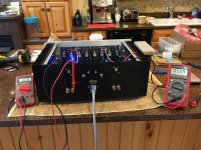
Reconnected meters to read across source resistors and just started turning pots ... until ... LIFE!!! It's alive!!!
It's warming up for now but now I'm curious if maybe the Cree SiCs would have worked if I just dialed up the VGS ...
Anyway, my problem now is there is no home for F6 boards. I will have to evict someone from the case or I need to find space for another amp ...
Poor F4 has been sitting in cold basement for over a year with no activity 🙄
I have taken voltage readings across the LED string and see 5.54V on both sides, is that too low? These are supposed to be 3.4V LEDS but that is now in parallel with 5K pots. Transformer is 18+18 and PSU is putting out 25.4V unloaded.
jfets are from my own hoard from long long ago in a galaxy far far away ...
Thank you 1543 for the jumpered P3/P4 link - verified my jumpers are done correctly.
Update: So instead of looking at screen with brain turned off just trying to see if I had bad connection or misplaced component, I thought about what I was trying to measure. Papa's original schematic says to measure 1.2V across gate and source ... isn't this VGS? So I checked Semisouth datasheet and indeed, VGS (threshold) is between 0.75V and 1.25V. IRF VGS is more like 4+V so instead of trying to find what's wrong with the board, maybe it's what I was measuring that was wrong.
Reconnected meters to read across source resistors and just started turning pots ... until ... LIFE!!! It's alive!!!
It's warming up for now but now I'm curious if maybe the Cree SiCs would have worked if I just dialed up the VGS ...
Anyway, my problem now is there is no home for F6 boards. I will have to evict someone from the case or I need to find space for another amp ...
Poor F4 has been sitting in cold basement for over a year with no activity 🙄
yeah ...... I'm realizing same thing - whenever I really engage my two cells , something positively happens
though , Mu state has its own merits

though , Mu state has its own merits
Thanks to your answer
Yes the pcb dont fit, but LL1690 the could be better than the jensen ?
what are the characteristics sought for the transformer?
the 1000uf capacitors are there for bias stability ?
Yes the pcb dont fit, but LL1690 the could be better than the jensen ?
what are the characteristics sought for the transformer?
the 1000uf capacitors are there for bias stability ?
Last edited:
HELP NEEDED! :-((
First I have to mention this is my first electronic thing ever build…
Input : 25,5 V supply ,when loaded ! (I hope is not too high)
caps 15000µF 35V
toroidal 400 VAC , 230 V to 2x18V AC
fuse 1,25 A fast blow
JFETS (not matched unfortunately…) is that so important?
LSK170 B 0,43V / 0,6 mA
0,43V 7 0,61 mA
LSJ 74 A 0,36V / 0,5 mA
0,35 V / 0,5 mA
Hi all,
I just finished my F6 and I have performed some tests.The results are as follows:
a) Before bias:
- 25,5 V on load with small variations +- 0,1 or 0,2 V ;
- blowing fuses when shut down! I have changed several 1,25 A fuses ,fast blow, and it happened all the time ,but only at shut down.
- I have connected a pair of speakers and apart from music I have noticed a buzz. Ok, I understand is because of bias needed. I had the trimmers – bias and offset- set in the middle.
b) During bias:
- Unfortunately I didn’t understand how to set the trimmers and I have fully opened them.The result was a to much current and …smell…I had more then 2 V over the 0,47 resistor when I switch it off immediately. I have disconnected the LH branch and I have tried to bias the RH side after I set the trimmers to maximum (fully turned clockwise …). I have started from 0V on 0,47 resistor , in paralele with offset, and I have reached at 0,48 V and 65 degr C at the mosfet middle pin. The offset varied with 0,005 – 0,010 V , so it was not quite stable . The heatsink was worm.I have shut it down and tried to switch it on again. This time the fuse blown right from the biggining .I have tried with a 2 A slow blow ceramic fuse and is not blowing anymore.I have measured again the voltage on the 0,47 resistor and…I have something like - 0,45 V ( minus ???)
- I have connected the LH branch and I have measured the voltage on 0,47 resistor during bias.It remains 0V whatever I do, so I guess something is burned. The Led on this side was not working from the biggining ( only on supply and RH side was ok).
So …any suggestion?
Thanks
Attachments
Thank you,
should I add a resistor on the Jfet source maybe ?
to reduce the idss of 2mA the resistor at 23V should be 11.5 Ohm. Am I right?
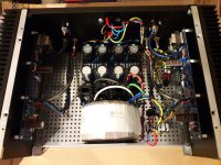
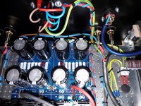
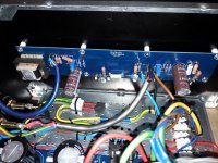
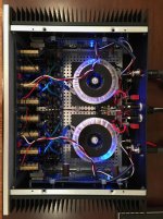
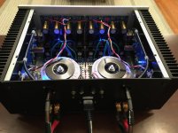
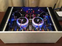
Finished my F6 yesterday. It is a very standard build that won't impress anyone except my wife and friends. But I am quite happy with how it turned out. I have built a Bottlehead S.E.X. and WHAMMY headphone amp recently but this was the biggest DIY project I've done. So I had a big sigh of relief when the power supply and then each channel fired up on first try with no issues. Many thanks to 6L6 for the detailed build instructions that were priceless, along with all the questions and explanations in this and other First Watt threads. And of course huge thank you to Nelson for being so generous with his designs and intellectual property. I was somewhat concerned about whether it would drive my medium efficiency speakers but I shouldn't have been. With my Pass Labs XP-10 preamp in a somewhat small listening room it has way more power than necessary and drives my Harbeth speakers wonderfully. Still have some clean-up to do on the wiring as it is not quite as clean looking as I was hoping, but the amp is dead quiet as is. And my wife is quite happy to have her kitchen island back. 🙂
Attachments
I would say it looks mighty fine as is and that a lot care went into its construction.
Congratulations and enjoy!
Of course, now that you've discovered you don't need too much power, you
may wonder how the other FW amps might sound.... 🙂
BTW, which Harbeths are you using?
Cheers,
Dennis
Congratulations and enjoy!
Of course, now that you've discovered you don't need too much power, you
may wonder how the other FW amps might sound.... 🙂
BTW, which Harbeths are you using?
Cheers,
Dennis

Quick question regarding the bias. I notice the amp was running much cooler than I anticipated. When I reread the bias instructions I noticed 6L6 says to measure across the 0.47R source resistor (R2). I measured the voltage across the 0.56R source resistor (R1) as they are easier to reach. Hence, instead of 1.06A bias (.500mV / 0.47R) I have actually biased it to .89A. Is my logic correct? When I try to bias using R1 I run out of range. The highest I can get is .425mV with about -3.2mV DC offset. The values for R7 and R8 are 3K3. I believe Z1 and Z2 are 5.1V (that is what is listed for the F6 transistor kit I purchased from the DIYAudio Store). I assume this means I need to swap out Z1 and Z2. Is that correct? Or can I adjust the values of R7 and R8 instead?
- Home
- Amplifiers
- Pass Labs
- F6 Illustrated Build Guide