DC but not AC. The AC degeneration is important to get a strong dominant second Harmonic.Lol...
No.
The DC degeneration will still be there.
Read my blog and watch the video of me demonstrating this on the distortion analyzer
If you can set bias and offset properly, no.
😀
Thank You!
Setting.. I have experiences with . Was concerned if I needed to spend the same for 2 pair of matched 240s' as Mouser charges for 24 ! of the rascals.
Frugal by necessity (retired) are us 😱
You don't need matching.Thank You!
Setting.. I have experiences with . Was concerned if I needed to spend the same for 2 pair of matched 240s' as Mouser charges for 24 ! of the rascals.
Frugal by necessity (retired) are us 😱
Very nice Christmas present.
I think rerouting cap leads to the other side of source resistor only for the bottom Mosfet will generate positive 2nd harmonics for matched pairs. Maybe too much?
I think rerouting cap leads to the other side of source resistor only for the bottom Mosfet will generate positive 2nd harmonics for matched pairs. Maybe too much?
You can do one or both.
Doing one might generate too much 2nd harmonic with 0.47 Ohms source resistance, but maybe not, that will depend on your ears, your music, your speakers, and how loud you listen to music. All of that will be a factor.
Either way it will still be less distortion than the SIT amps (if my memory serves correct)
I can check my log book of results when I get home.
It really doesn't hurt to try it.
If you can also rig up a trimpot on the device that would be the ideal situation.
Last edited:
I am afraid using trim pot will affect DC degeneration also.
I thought we needed DC degeneration for IRFP240s for stability reasons.
What is the minimum source resistor size required for the stability?
I thought we needed DC degeneration for IRFP240s for stability reasons.
What is the minimum source resistor size required for the stability?
Trimpot is in parallel with 0.47 Ohm resistor. Cap lead goes to wiper of trim pot.I am afraid using trim pot will affect DC degeneration also.
I thought we needed DC degeneration for IRFP240s for stability reasons.
What is the minimum source resistor size required for the stability?
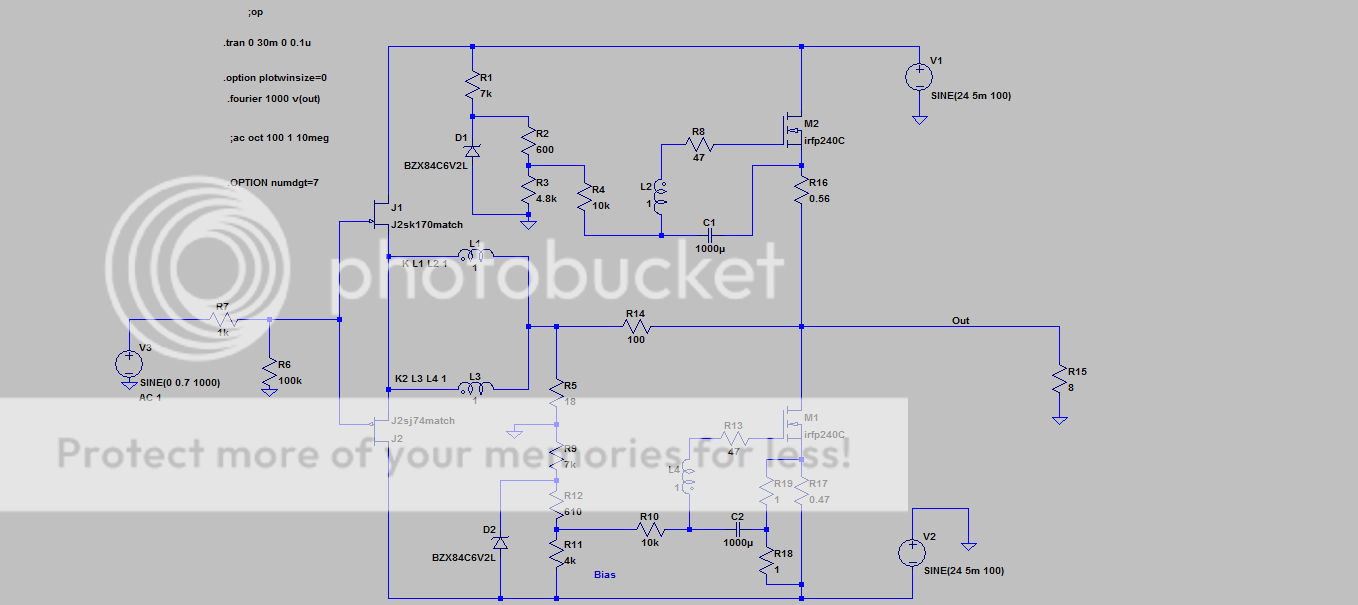
You have both DC and AC degeneration like that
Or if you have some 3w resistors anywhere between 1 Ohm and 5 Ohm you can something like this.
Probably change R17 to 0.56. There is some flexibility
Probably change R17 to 0.56. There is some flexibility
Last edited:
In the end probably a lot easier to just move both cap leads and choose your source resistors appropriately
Last edited:
Hello Guys.
I'm very interested by the F6.
however I find interesting that the suggested mosfet is a switch one... IRFP240.
How close the the THD gets to the original power jfet proposed by Mr. Pass.
I was wondering if anybody tried a lateral mosfet like ( ECX10N20 or ALF08N20V ).
Thanks in advance.
I'm very interested by the F6.
however I find interesting that the suggested mosfet is a switch one... IRFP240.
How close the the THD gets to the original power jfet proposed by Mr. Pass.
I was wondering if anybody tried a lateral mosfet like ( ECX10N20 or ALF08N20V ).
Thanks in advance.
Hello Guys.
I'm very interested by the F6.
however I find interesting that the suggested mosfet is a switch one... IRFP240.
How close the the THD gets to the original power jfet proposed by Mr. Pass.
I was wondering if anybody tried a lateral mosfet like ( ECX10N20 or ALF08N20V ).
Thanks in advance.
The production Firstwatt F6 Amp uses IRFP240, so no need to lose sleep.
The production Firstwatt F6 Amp uses IRFP240, so no need to lose sleep.
Thanks.
My F6 build
My F6 build, ordered F6 kit on 12-12 and received the boards and transformer on 12-19. I converted my BA-2 build to the F6, so chassis and power supply were already available. My BA-2 used + - 50 volt rails so wired the antek for 240 volt and got the +- 25 volt rails.
The following are the results of the F-6 build.
let cook for 4 hours biased the amps at 0.610v with offset of 2 to 3 mv FETS got up to 50 c.
Testing with meters, signal generator, and Scope.
Left channel
Bias (cold) 0.493v
Offset (cold) 28.4mv
Right channel
Bias (cold) 0.51v
Offset (cold) 25.4mv
At 30 minuets
Left
Bias 0.595v
Offset 3.8mv
Right
Bias 0.592v
Offset 1.7mv
At 1 hour
Left
Bias 0.617v
Offset 6.2mv
Right
Bias 0.619v
Offset 2mv
Power supplies at full bias +- 22.2v
No load clipping 41.2 v peak to peak
Measurements with 4 ohm load, voltages are peak to peak from scope at 1KHz.
Left channel
Input Output Bias
0.29v 1.37v 0.606
2.84v 13.45v 0.618
5.66v 26.15v 0.67
Right channel
Input Output bias
0.286v 1.43v 0.605
2.84v 13.7v 0.615
5.65v 27.15v 0.67
At soft clipping top of sine wave just starting to change shape.
6.5-7.6v 34-36v 0.8+ Left
6.5-7.6v 34-36v 0.8+ Right
Let smoke out of right channel 0.47 ohm resistor. All measurement with one channel driven. Measured current on one channel with meter 10 to 12 amps at soft clipping.
Comments: First impression with DIY speakers very good detailed sound whereas BA-2 was a softer presentation. Will install on big speakers ( Maggie 1.7 and Tannoy DC10A) to get a better handle on sound.
The preamp will need to output around 4 to 5 volt RMS to achieve full output from the amp at current gain setting, which may be a problem for some pre’s. Also if you are going to drive 4 ohm or lower loads at close to full output then need to parallel the bias resistors to get 6 watt or higher wattage. May be a good fit for Caddock resistors (May try to order some to try out).
My F6 build
Spent about 4 hours listening to F6 driving Magnepan 1.7, with Primaluna Dialogue premium preamplifier. Had to run the preamp at max level to get sufficient output from the 1.7, but I don’t know what the primaluna max output level is (spec’s say 4 volt but do not know if this rms or whatever). The F6 is a very good amp, and now I know what the first watt amps are all about. Imaging and detail very tube like with good depth and width very listenable with low fatigue. Thanks to PaPa Pass for another excellent design. Actually I am surprised the F6 drove the 1.7 as well as it did as they eat power for breakfast. Will hook up the Tannoy DC10A (sensitivity 93 db at 8 ohm) and see how they do in next couple of days. The Tannoy’s can be a little relentless with tipped up upper mid range.
Design questions :
My measured gain left was 4.73 or 13.49db and right was 4.82 or 13.66db according to F6 article gain was set to 5 with a 50kz bandwidth, my question is does anyone know what the bandwith would be with a gain of around 7 or 16-17 db. It might soften up the treble but that may not be a bad thing with some speakers and would increase gain to give more control to some preamps. Hey it’s diy so why not tune amp to speaker.
Just ordered all the bits For F6 AND for the PS from Mouser ... Using the BOMs.
Small issue 🙂
I don't have a DIY audio PCB (yess forgot to order it along with the F6 'kit')
So... Not overly keen on the 20$ Postage.. for a PCB.
Any obvious problems using the Schematic on a Perf board and wires?
Only a Transformer and a pair of Heatsinks to go.
Small issue 🙂
I don't have a DIY audio PCB (yess forgot to order it along with the F6 'kit')
So... Not overly keen on the 20$ Postage.. for a PCB.
Any obvious problems using the Schematic on a Perf board and wires?
Only a Transformer and a pair of Heatsinks to go.

my F6 buil
Hooked up Tannoy DC10A, ( 93 db sensitivity) an excellent match, better than my Primaluna Dialogue tube amp for these speakers, better bass control and mellow upper mid with detail. Level adjust-ability with amp gain of 5 is ok with Primaluna preamp. I left the bias set at 0.59v after measurements may bump it up to 0.619v and measure temp with amp installed in rack to see if I can tell any difference in sound.
Hooked up Tannoy DC10A, ( 93 db sensitivity) an excellent match, better than my Primaluna Dialogue tube amp for these speakers, better bass control and mellow upper mid with detail. Level adjust-ability with amp gain of 5 is ok with Primaluna preamp. I left the bias set at 0.59v after measurements may bump it up to 0.619v and measure temp with amp installed in rack to see if I can tell any difference in sound.
- Home
- Amplifiers
- Pass Labs
- F6 Illustrated Build Guide