Here is the difference in regulation between 9.1V Zener and Zen Mod's 5.6V Zener circuit.
It's possible you might be experience this issue, your speakers are quite sensitive.
Get rid of the 9.1V Zener.
I have 5.1V zeners on the way as the idss values of the IRFP240's I am using are low - 4.165/4.164/4.163/4.164.
Could this explain the noise? Why one channel only thought?
I have 5.1V zeners on the way as the idss values of the IRFP240's I am using are low - 4.165/4.164/4.163/4.164.
Could this explain the noise? Why one channel only thought?
Possibly transconductance variations. Higher transconductance devices will conduct more current with changes in Vgs. The dc offset will also oscilate with greater magnitude if there is an imbalance of transconductance between devices.
Hopefully this is what you are experiencing, 95dB speakers are more prone to these issues. Either way changing the Zener is a step in the right direction.
Last edited:
Just one more thing, check that all your ground connections are all nice and tight and/or nicely soldered.

Day 3
what happens when you disconnect input cables from amp and put shorts on input RCAs ?
When I disconnect the input RCA's the noise level in the right channel increases substantially (the left stays dead quiet when doing this). When I plug in a shorted input RCA - the noise goes back to the same volume as with normal RCA's from my source, no difference.
As you know it could be a number of things but my first thoughts are it is a loose connection or cold solder joint. I've experienced it a few times with temporary builds moving them around testing and a wire became loose or undone. Re solder the rca connections to the connectors and boards first is what I would do before digging further. Try simple things first. If it was quite at the beginning and noisy now I would be suspicious of the input and output connections. Plugging cables in and out will sometimes reveal bad joints.
RCA joints look very solid. Measured 5 ohm between RCA GND and chassis (due to thermistor?). Also tried using the GND from the left channel PSU (and also direct to chassis GND) and same issue. The issue seems local to the right amp PCB. Tried lowering the bias and double checking DC offset but also no impact on the noise. 
Try shorting the input at the board that way you will know which way to look. If you still have noise it is going to from the board forward. We are trying to find which circuit the problem is in.
If you still have noise after shorting at the board what I would do is to take a soldering iron and go over all the joints on the board in question. I've had a number of the cheap Chinese boards to give problems but worked fine after doing this. If that does not fix the noise we have to look elsewhere, maybe a part on the board but the F6 board luckily has very few parts. The jfets or capacitor are usually suspect first if it is not a bad connection elsewhere.
You may want to take a pencil with an eraser and tap the components with the eraser and see if it changes the sound any. Just things to do without oscilloscope and generator.
You may want to take a pencil with an eraser and tap the components with the eraser and see if it changes the sound any. Just things to do without oscilloscope and generator.
Last edited:
Also try moving all the wires around and rotate the PS transformers. Be sure no PS wires are around the audio transformers. The solution is somewhere so do not give up.
I've had success with that trick in the past.You may want to take a pencil with an eraser and tap the components with the eraser and see if it changes the sound any. Just things to do without oscilloscope and generator.
Another possibility is the powersupply caps.
Either failure or bad solder joint. I'm not sure how robust your caps are to inrush currents
Try tapping each one with the eraser like mentioned above.
Either failure or bad solder joint. I'm not sure how robust your caps are to inrush currents
Try tapping each one with the eraser like mentioned above.
Last edited:
Thanks for all the suggestions.
I tried shorting the audio input at the board and this had the same effect as plugging a shorted RCA cable in the back, the noise remains.
Tried tapping all components on right PSU and amp board and this did not help.
I just wired the left PSU (it is a dual mono amp) to both left and right channels and the noise remains in the right channel, I guess this rules out the PSU and something is going wrong within the right channel amp PCB.
Next step is to remove the amp PCB, check solder joints, replace JFETs (fortunately I have another pair on hand), replace caps, and while at it do the other tweaks needed which was replace 9.1V zeners with 5.1V zeners, and flip polarity of one of the LEDs, likely unrelated to the noise issue. Will check back in a few days with hopefully some good news and the culprit identified.
Next step is to remove the amp PCB, check solder joints, replace JFETs (fortunately I have another pair on hand), replace caps, and while at it do the other tweaks needed which was replace 9.1V zeners with 5.1V zeners, and flip polarity of one of the LEDs, likely unrelated to the noise issue. Will check back in a few days with hopefully some good news and the culprit identified.
I would hold off on replacing jfets. Wait till you've replaced Zener.
With a multimeter you can measure Vds and Vgs on each jfet.
Progress at least, you now know what it is not. Trying touching the iron on solder joints before replacing anything other than led. Repairs are sometimes a process of eliminating what it is not.
D
Deleted member 24284
I just missed out on the PC board purchase. I can wait for the next batch. Or just wire it up on a terminal strip, building it like an old-fashioned tube amplifier, with a perf board used for the smaller components.
http://www.tubeampdoctor.com/images/products/HR9207.jpg
http://www.circuitspecialists.com/content/111731/64-8932-0.jpg
One suggestion I have regarding using a PC board or not using it: I prefer having shorter wires throughout the amp. To do that, I want to put each output transistor on its own heat sink. That lets me put all the components within a 2"x2"x2" cube, except for the power supply filter caps, even if wired on a terminal strip instead of a PC board. The filter caps can go underneath this cube.
I will build it in a mono block configuration, so there will only be two large heat sinks per chassis.
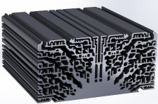
I wish mega heat sinks like the following are commercially available:
https://blogs.mentor.com/robinborno...mi-therm-31-dolly-the-heatsink-and-much-more/
http://www.tubeampdoctor.com/images/products/HR9207.jpg
http://www.circuitspecialists.com/content/111731/64-8932-0.jpg
One suggestion I have regarding using a PC board or not using it: I prefer having shorter wires throughout the amp. To do that, I want to put each output transistor on its own heat sink. That lets me put all the components within a 2"x2"x2" cube, except for the power supply filter caps, even if wired on a terminal strip instead of a PC board. The filter caps can go underneath this cube.
I will build it in a mono block configuration, so there will only be two large heat sinks per chassis.
I wish mega heat sinks like the following are commercially available:
https://blogs.mentor.com/robinborno...mi-therm-31-dolly-the-heatsink-and-much-more/
Attachments
Next step is to remove the amp PCB, check solder joints, replace JFETs (fortunately I have another pair on hand), replace caps, and while at it do the other tweaks needed which was replace 9.1V zeners with 5.1V zeners, and flip polarity of one of the LEDs, likely unrelated to the noise issue. Will check back in a few days with hopefully some good news and the culprit identified.
It was the JFETs! Replaced with a different pair and now the channel is quiet.
Interesting. That wouldn't normally happen if they were working ok to begin with.It was the JFETs! Replaced with a different pair and now the channel is quiet.
What was Idss of the old jfets?
- Home
- Amplifiers
- Pass Labs
- F6 Illustrated Build Guide